Well, it has only two channels - which is in fact, all you require for the overwhelming majority of I²C situations.
The regulator is useful as well. I'm not sure it would matter if you did feed it 3.3 V as well as 5 but it would generally be a better regulated source than from the USB chip in some clones.
The problem is I am not at home, I’m in another city and I cannot buy one here. Is there anything I can do to fix it except buying the regulator?
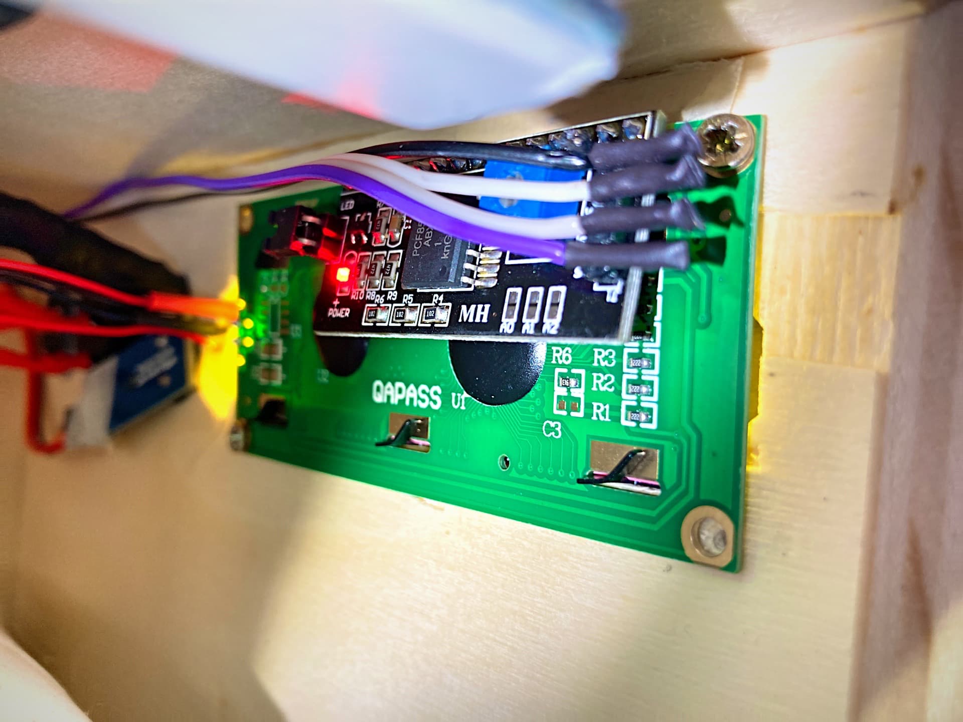
The wires are connected into a terminal block with screws so the connections are good and the LCD came with pins already soldered to I2C from the factory.
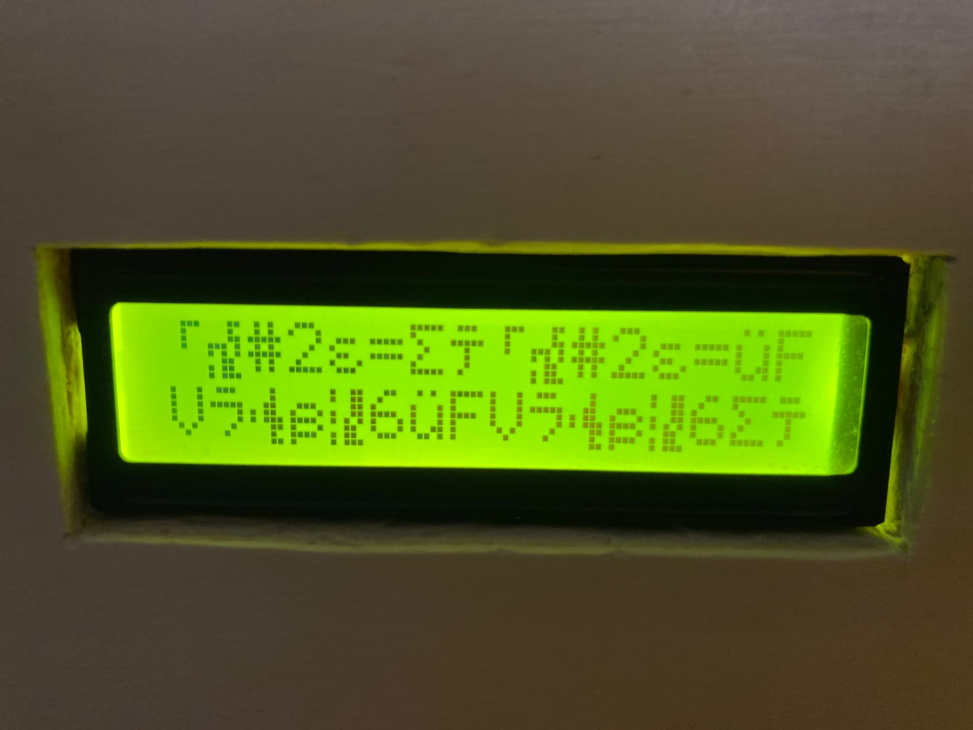
Also I just cut the dupont wires connected to I2C and soilder the wires to pins very well, but now the strange characters apear even more often.
The good part is that at least with this new library the image comes back after about 1 minute.
I just found a buck converter into my toolbox, I took an external power supply, set the buck converter from 12v to exactly 5v and connected the + to I2C and the - to ESP ground. Now I don’t see the strange characters that often but they still appear after a few minutes. What may be the cause?
I saw that the strange characters begin on the screen on the temperature sensor value, maybe there is some interference with DS18B20 sensor which also uses the wire library.
I would be more worried by external relays, switches, ...
External electronics are more likely to introduce electrical noise. Especially coils and inductors.
Thank you, but now the LCD is connected to power from an external supply with a buck converter. Only the ground is common with the developing board. It may still get electrical noise?
What loads are you switching with those relays? Inductive loads are worse for inducing transient power effects than pure resistive loads. Does simply disconnecting the load(s), keeping the relay module connected, also solve the problem ?
The loads are 2 AC devices (a lamp and electric heater) and 2 DC devices (PC fan and a 12v pump). I tried with an SSL relay, but the DC loads did not work, it only connected the AC ones, I didn’t know that SSL relays only work with AC loads.
I would think it could be an issue.
It would be hooking up the 3v output from the Arduino board 3v regulator to the 3v output of the level shifter 3v regulator.
i.e. it is connecting the outputs of two different 3v regulators together.
OK. The pump and fan will certainly be inductive so it could be worth just temporarily disconnecting these from the relay module to see if it has any impact on the problem.
The relay module can be powered powered by 2 different supplies. Vcc and JD-Vcc are separate. See the schematic in this link: 4 Channel 5V Relay Module - Wiki.
Incidentally, I've never previously seen a level shifter with a built-in regulator. I suppose it could be useful if you are connecting a 3.3 volt peripheral to a 5 volt Arduino (which you are not doing).
It is quite useful for 5v master to low power 3v slaves since you just hook the device to power on the 5v side and the slave can get its power from the 3v side.
But as you said in this case it is a 3v master to 5v slave.
However, it is still useful in this application as it removes one wire connection.
The 3v pullups are on the level shifter and get the 3v power from the on device regulator.
In post #29 Seems like you kind of already showed it is related to the relays and switching.
Now take a step back way back.
We need you to fully disclose everything you are doing.
You started off telling us some things in your original post.
But you have now disclosed that you have more components than what you originally stated.
Details really matter. Had you originally told us about the relays we would have gone down different paths to try to find the issue as using relays has many known issues.
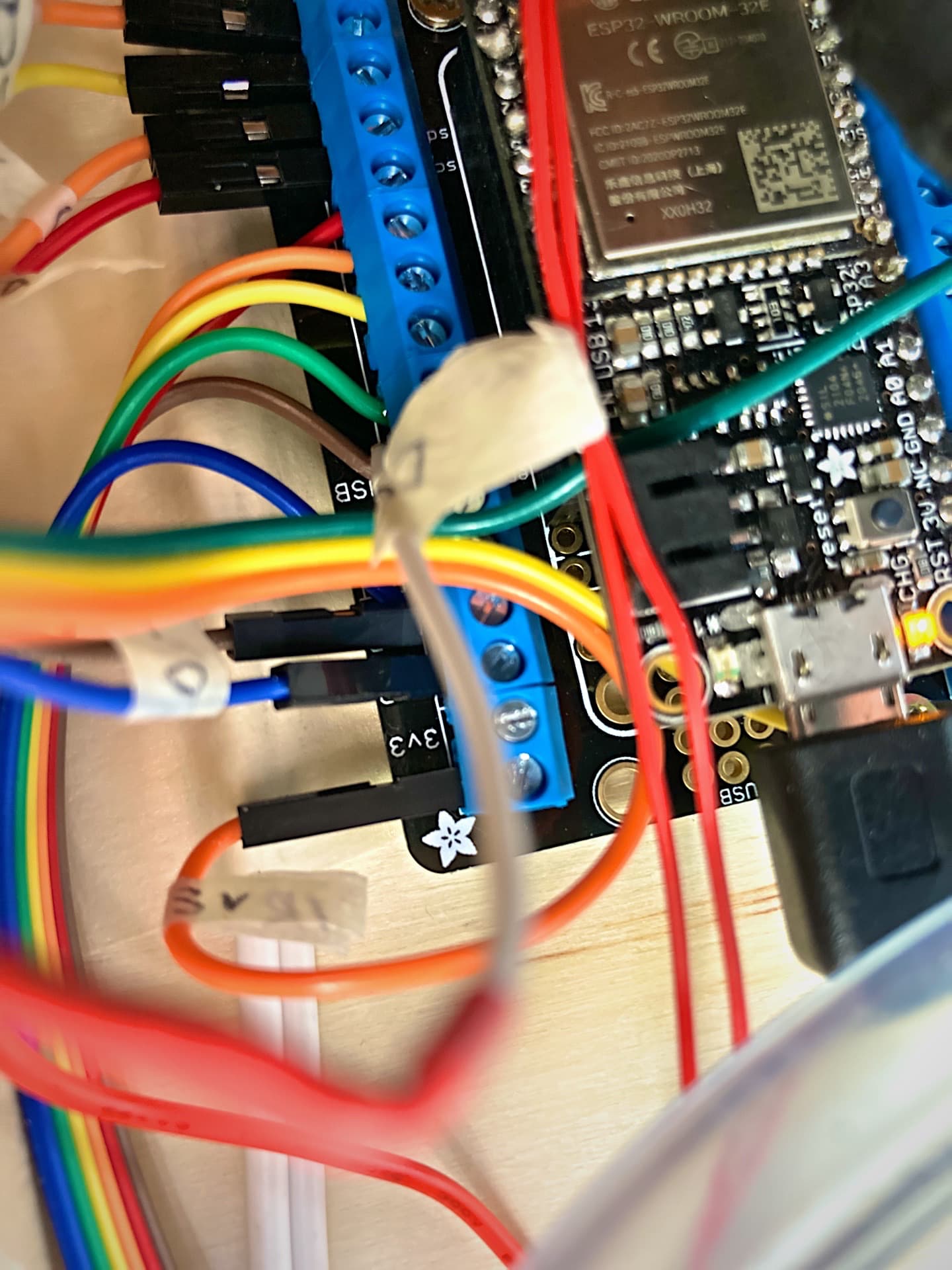
Please now post a full details of what this project/code is doing along with a full schematic of everything you have connected and show a few pictures of your project so we can see how things are wired up.
By the way, no need to delete posts. There is a "pencil" icon below your post which allows you to edit it.
Just don't change older posts in a way that makes later comments look silly. You are always welcome to add code tags to code that was previously posted without them.