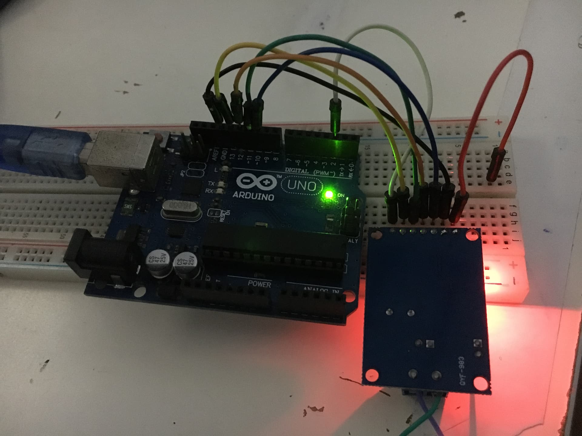
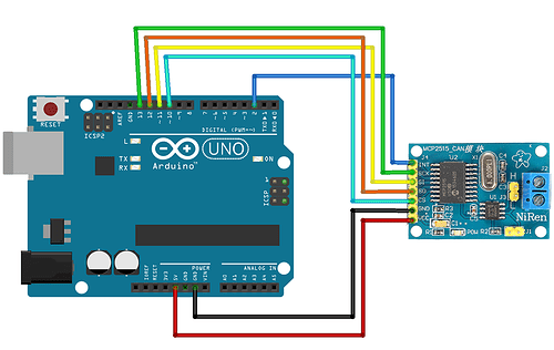
And I'm seeing the MCP2515 module is receiving power without the VCC conenction. See below two images of the actual cuircit.
How is this possible?
Any ideas?
When I disconnect the SCK line, power goes off to the module.
The module is being powered through the input protection diodes, which can damage both the Arduino and the module. As a general rule, you should not connect powered devices to unpowered devices through I/O lines.
As you found out, the power is comming from the SCK line maybe also the CS line.
This will happen because the 5V on the SCK line is powering the circuit through the ICs internal protection diodes.
Doing this can destroy either or both modules.
Gil's Crispy Critter Rules, they apply to processor hardware:
Rule #1. A Power Supply the Arduino is NOT!
Rule #2. Never Connect Anything Inductive to an Arduino!
Rule #3 Don't connecting or disconnecting wires with power on.
Rule #4 Do not apply power to any pin unless you know what you are doing.
LaryD's Corollarys
Coro #1 when first starting out, add a 220R resistor in series with both Input and Output pins.
Coro #2 buy a DMM (Digital Multi-meter) to measure voltages, currents and resistance.
Violating these rules tends to make crispy critters out of Arduinos.
okay, but then how would you suggest I connect the Ardunio SPI lines to another SPI module?
I never intended to power a module through Arduino IO pins.
I was puzzled when I saw the moudle power led is on when I removed the vcc and gnd line from the module.
SPI, I2C and other systems are designed for use on the same board, not to communicate between different boards. There is CAN, Several RS protocols, RF etc that will work much more reliably between boards. You can use a bike to ride for about an hour go get a cup of coffee or take a car and get there in a few minutes. They both will get you there but in a freezing rain which would you prefer.