I created a custom ESP32 C3 board and I am using an external USB to UART board to program it.
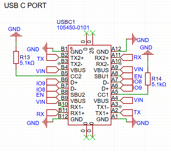
I am using a USBC port to power the project, so decided to use the other pins to pass the enable pin (EN), and boot mode pins (IO8 and (IO9); however, I am having reliability issues. The connector has to be put in just the right spot with my mating device, and program uploads frequently fail. An image of my schematic is below.
Is there anything inherently wrong with what I am doing with this project or do I just have to shop around for more reliable USBC connectors. AKA: Is a usbc port designed to pass serial communications through it? I am not using the differential pins so I wonder if I just have a poor connection due to that.
Also, the power connection is very consistent and I have never had issues powering the project, but I do notice that the connector will eventually wear out and stop working with the programming board.
Hello!
For the questions above:
I am using a module on a custom development board.
I am using the pins for non-usb purposes. Just trying to use them as digital pins to interface with the module.
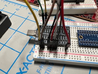
I am not using a cable per se, but a male usbc breakout board to connect to my USB to UAET board.
What I am trying to do is use the USBC port as a pass through for connections to parts of my board, but I am having issues with the signal integrity. I want to know if this is a common use for a USB port and if I should be using differeicital signals or something to ensure I have a good enough connection.
Let me know if what I am doing should be able to send serial communication and controlling pins high and low or if I should be doing it with other circuitry.
My goal is to use this board as a custom bare bones development board. On the next iteration I will add thermistors and the board will be used to measure temperature. I plan to have it connected to wifi and additionally have a screen.
Why I don’t use a standard dev board or copy the one online is that I want to learn and make something that works exactly with my intended use.
I am using the Arduino IDE to program it. To be clear, it had worked, but it is very unreliable.
The male connector I had in the picture above connects to the schematic I made.
For a usb to uart board, I have a ESP32 dev board that I removed the ESP32 from and I am just using the chip on that board.
An ESP32 has an absolute A/D and is therefore not very well suited for thermistors.
You need a ratiometric A/D for that. And there is the poor linearity of the A/D of an ESP.
Digital temp sensors are much better suited for the ESP32.
Like the DS18B20 (-55C to +125C). Many of them can be connected to a single pin of the ESP.
A screen can be I2C or SPI and only uses two or three pins.
I think you mean the ESP module (metal box). An ESP chip is about 2x2 mm.
I see other threads from you with bits and pieces of a project.
You will get better help if you explain and post your whole project.
Leo..
At the moment I am looking for advice regarding my usage of a USBC port. As it has 2 banks of 12 pins I am trying to use it as a connector to interface with my board while keeping my interface very simple for the final product.
From what I can tell there is nothing I am doing completely wrong with using a USBC port as a a pass through instead of USB functionality, but I do believe I still need the R13 and R14 resistors to ensure that the power supply will deliver power.
Either way, sounds like I should get a higher quality connector and try again.
Are you meant to be using D+ connected to IO9 as I think it should be IO19, and the same for D- not on IO8 but on IO18. Though you said it worked before so maybe your diagram is wrong.
Also, do you have ESD protection on the D+ and D- lines?
I went ahead and ordered a development board with this configuration and it is working great!
I can program and power the board through the usbc connector, and when I plug it in to a power only connector the board starts right up.
The serial connection can sometimes fail, but this may be due to my old breadboards.
@stem_forge78 I connected the D+ and D- pins through io8 and io9 because I am not using them for USB purposes. They are just being used to access these pins on the board without needing an additional connector.
I am not using esd proctor currently on these lines which is something I should consider adding.
I will have to do some testing with different cables and power supplies to make sure that when I use a full data cable the devide will still work as expected, but for now I am happy.
I am using a ESP-WROOM-32 ESP32 ESP-32S Development Board (which I removed the ESP32 off of) just to hijack the serial to UART converter and the built in logic for DTR and Enable.
The only thing that I have to do is ground IO9 (I put a button for that) to put it into boot mode. I have it pulled high so it goes directly into boot mode.
Something else that is interesting is the UBSC connection is working much more reliably now. I changed the female connector to a G-Switch GT-USB-7062 which is more expensive and presumably higher quality than the previous one I had on there. That was likely the source of my poor connection.