But I'm not able to answer and to open the door.
I tried to set the digitalWrite(Answer,LOW); and digitalWrite(Answer,HIGH); but nothing changed.
If you have any idea it will be great.
Thank you!
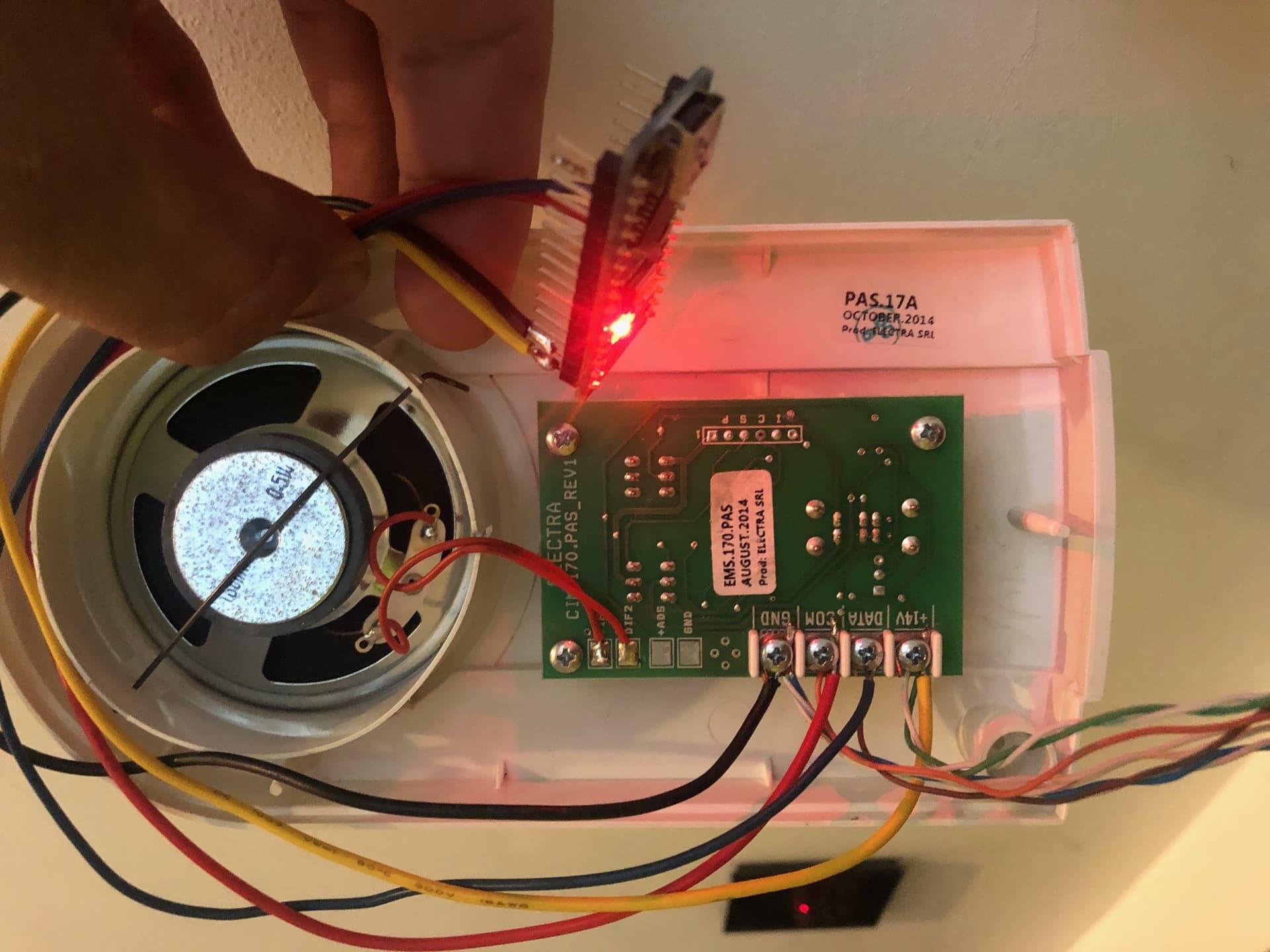
Hi, I managed to capture with an oscilloscope the signal the interior post is generating on DATA line when answer button is pressed and also when unlock button is pressed. I'm able to simulate those signals with an arduino but I'm still trying to figure out why this generated signals do not work as intended. I'll post the code if I figure it out. Meanwhile I can share those signals if there's interest.
What's weird is that the data line that enters the apartment (not the interior post data pin) is constantly outputing a 50Hz 90% duty cycle square wave while idle. When someone is calling that signal changes to a double square signal with a longer delay between each pair.
Also, when interior post is powered without the data line, there's no activity on the data pin and the buttons LEDs do not light up when pressed. If I wire the data line, button LEDs work but no signal is generated. Only when someone is calling those signal (answer/unlock) are sent on the same wire. So the weird thing for me is that the signal the interior post IC is generating is transmitted on the same line it's receiving. Did a google search and now I'm trying to understand 1 wire protocols.
Disclousure: I'm just an electronics hobbyist so any help would be well appreciated