Hi guys,
Maybe you can help me with the following situation.
There is an intercom installed at the entrance of the building where I live and a receiver in the flat.
When the number of the apartment is introduced the following sequence must be performed to open the external door:
-push the speak button (in this moment the ringing of the intercom stops)
-push the open button (the door of the building opens)
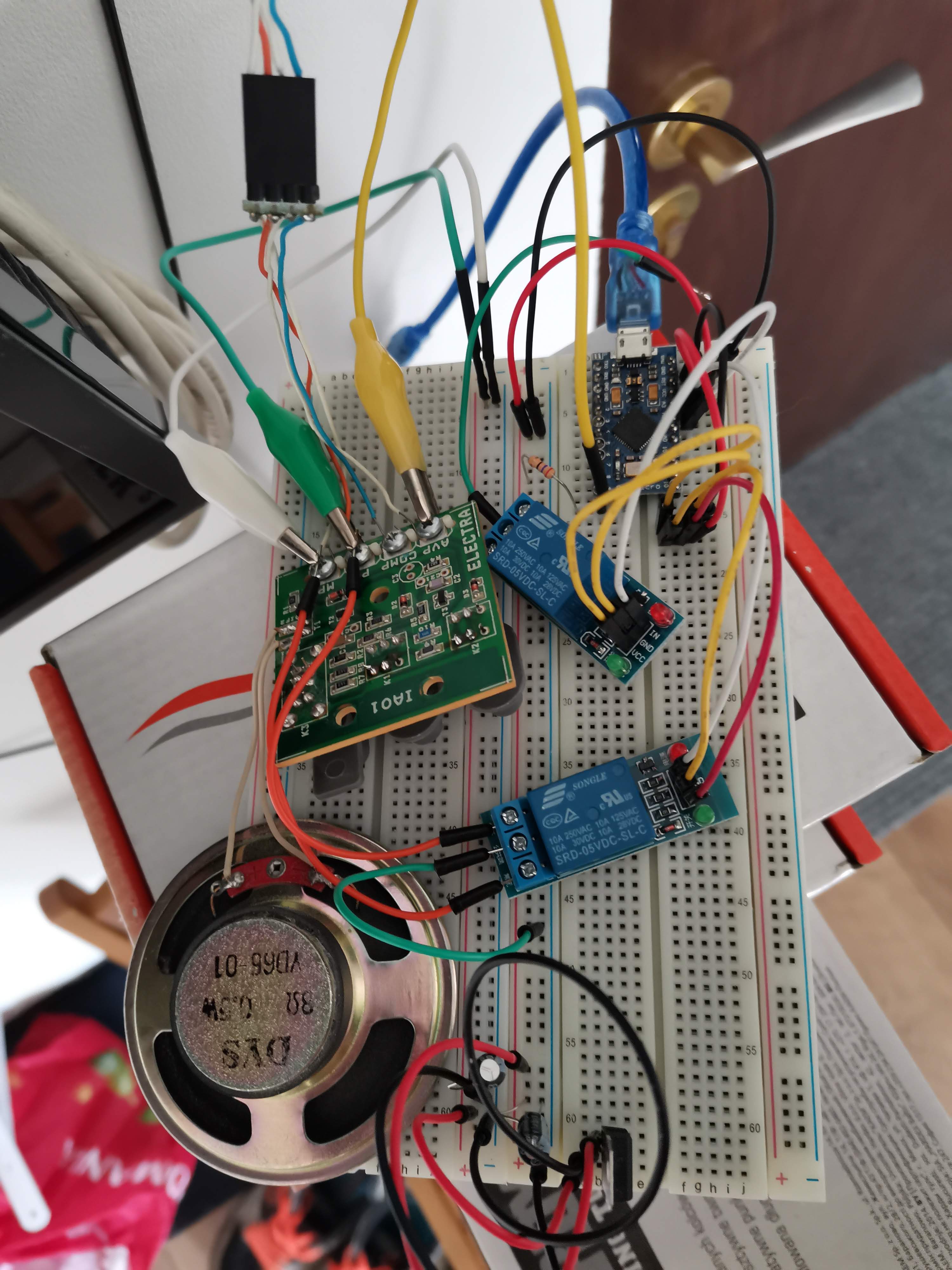
Before starting controlling this using a ucontroller (in my case an arduino nano) I wanted to "debug" what's happening there.
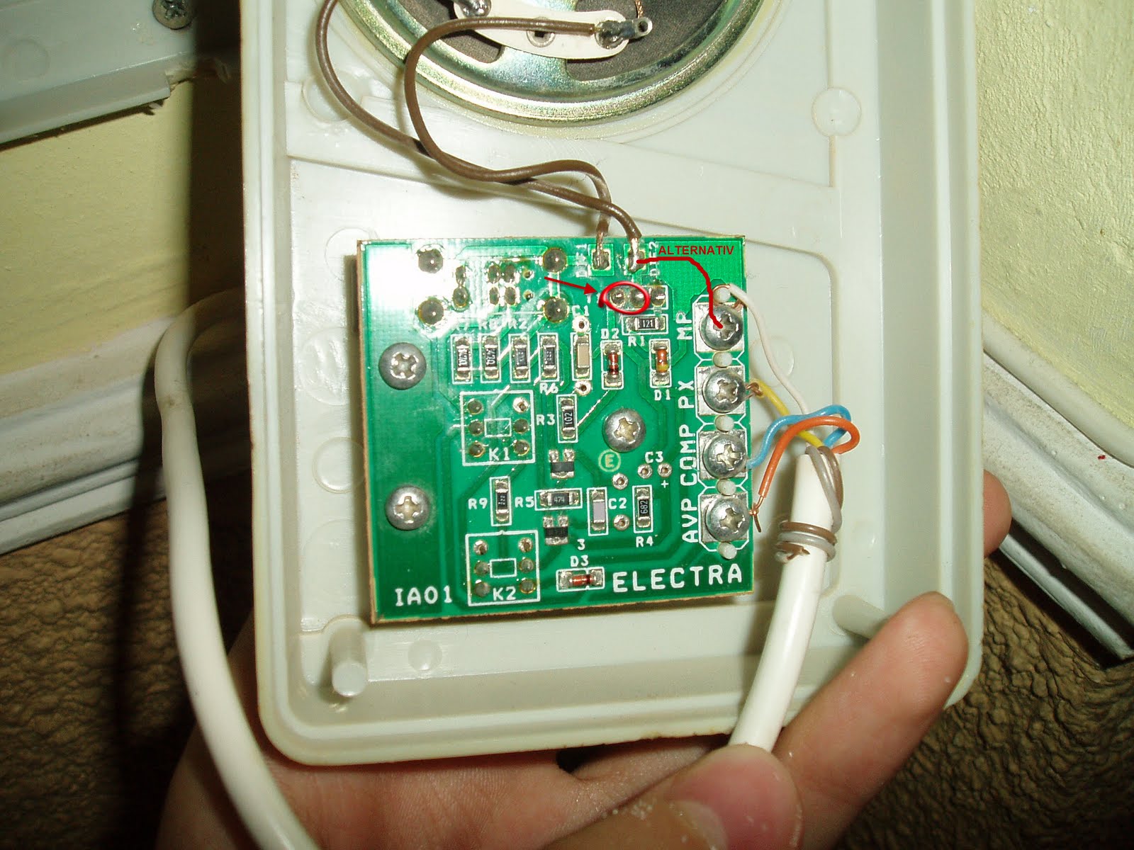
Here are two pictures of the scheme of the receiver:
-IA02-undressed (see attachment)
-IA02-circuit (see attachment)
Regarding the circuit I haven't spent to much time on it to understand every bits of functionality but rather I spent some time doing experiments.
According to the experiments the conclusions are:
MP - is the gorund
XP -is the VCC - 12 V
COMP - I didn't try any tests on it
AVP - Relay.
I made the following operations:
- while the intercom was calling at my flat, I measured between MP and XP (and I saw the voltages above), I measured between XP and COMP and AVP and the same voltage (12V)
I also measured between MP and -COMP and AVP: no voltage
When the talk button was pressed I measured between MP and AVP and I noticed a voltage of 5V.
Then when the open button was pressed I measured again between MP and AVP and noticed a voltage- around 5V.
Then I went on with the experiment:
- I took a phone charger of 5V and while the interfone was calling at my flat I put the negative terminal on MP and positive terminal on AVP. The ringing stopped.
Then without waiting a specific amount of time, I took the positive terminal off the AVP and the negative terminal off the MP and put them the following way:
-negative terminal of charger on XP
-positive terminal again on AVP
The result was that the door was opened.
I tried a similar experiment, keeping the positive terminal of charger on the AVP and just moving the negative between MP and XP and the result was the same - the door opened.
Another observation: I tried also to do the below operation twice (one for talk and one for open):
put
- negative on MP
-positive on AVP
I observed that the ring stopped when put the first time. Then when put the second time nothing
happened.
Some conclusions:
To open the door the sequence must be like this:
- first talk then open not reversed and not even only open.
- an impulse is necessary- to trigger talk, then to trigger open
-it's enough to keep a positive signal (not necessary 5V, it can be lower- I even tried with 3 V and 2V)
on AVP and just to swith the negative terminal from MP to XP.(the order is strict MP to XP)
How can this be achieved with an arduino NANO without additional circuits?
I saw that someone already did this and the connections are as follows:
-MP connected to GND
-XP connected to VIN
-AVP connected to D2
My question for this case with three cables is how the switching described earlier can be performed?
I generated a HIGH output on data D2 and the ringing stopped (this is equivalent to talk) then I generated a LOW , applied a delay of 1 sec, then reapplied HIGH -LOW sequence. The result was that
nothing happened.
As I said someone did this with three cables only.
So my final inquiry is how do I proceed with the nano?(something like a shifting negative pin or ground- the fact is that I see the result of the experiment but I do not understand very well what's happening so that I can apply the logic to the arduino device)
Any comments are appreciated.