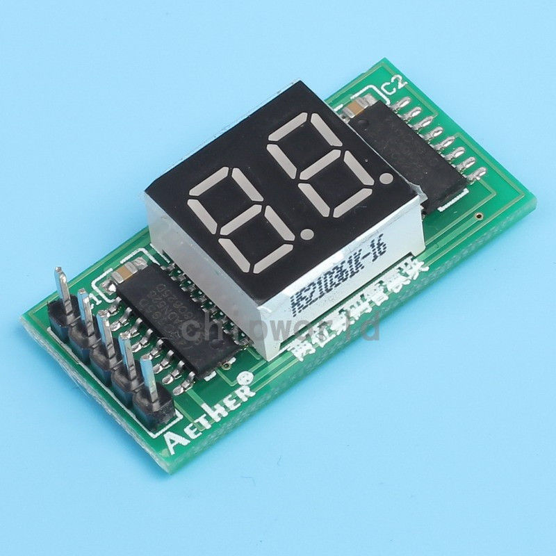
What a silly web page, in no way is this a Nixie Tube display. Can you say what numbers are on the two chips because that is a useless seller who doesn't know what he is selling.
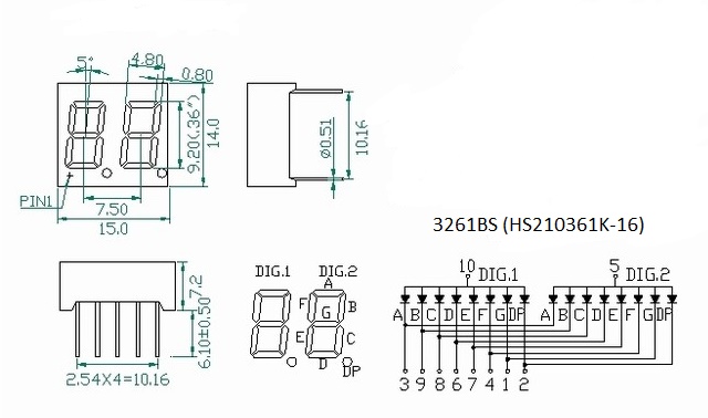
OK so my guess is that the shift registers simply connected to the seven segment displays. As a start I would use this tutorial to work out how the display is connected to the shift registers. The 74HC595 Shift Register | Arduino Lesson 4. Eight LEDs and a Shift Register | Adafruit Learning System
Using the code on the next page connect up :-
Arduino Pin 5 to the RCLK
Arduino Pin 6 to the SCLK
Arduino Pin 4 to the DAT
Arduino Pin GND to GND
Arduino Pin 5V to VCC
It is likely that one shift register is connected to one display.
I also think that multiplexing is necessary. I tried to find out the behaviour of the two shift registers. If I send 16 bits to the module and I send the same bit-pattern again, I get different results. Has anyone an idea about this behaviour?
Does anyone know an other two digit display which already has an bulit-in shift register?
Thank you
I'm a fan of the MAX7219
Use 1 IC instead of 2, use 1 resistor instead of 8
It can handle up to 8 digits per chip, only uses 3 wires (plus 2 power) to the Arduino even if you chain many of them.
Very strange. Are you absolutely certain that video goes with that sketch? Could you have mixed up the data, clock or latch pins? Are you sure the chips are 74hc595? (That is what I would have expected, but I can't read the markings on the chips in the pics on the eBay page.)
P.S. please learn to post code and links correctly.
@Axl please don't resurrect 2 year old threads from the dead, and please read the forum guidelines in the sticky post about how to post code correctly.