Hi,
So I am trying to use a relay to control some electromagnets, however I seem to be running into a couple of issues. I am using an Arduino R3, with an 125VAC 5 A Relay, and a 90 volt power supply with an electromagnet. I was following this turtorial: https://arduinogetstarted.com/tutorials/arduino-relay
And I have essentially the exact same wiring as shown near the end of the webpage. However, pasting their code, and recoding it myself, and switching pins doesn't seem to get the relay to work. The relay however, does seem to be receiving commands from the arduino, an onboard light shines green as progrtammed every half a second, showing it is receiving the "high" command, however it does not seem to excute it. Replacing the relay yeilds a simlar story. Does anybody have any resolutions or suggestions? Thanks.
No, the contacts inside are stuck together.
Remove the 90V and just try to click the relays. Your sketch looks appropriate for that much. Any click-clack from it?
I agree that the relay contacts are probably welded together, or if not, permanently damaged.
Switching DC with a relay is very different than switching AC, especially with an inductive load like an electromagnet.
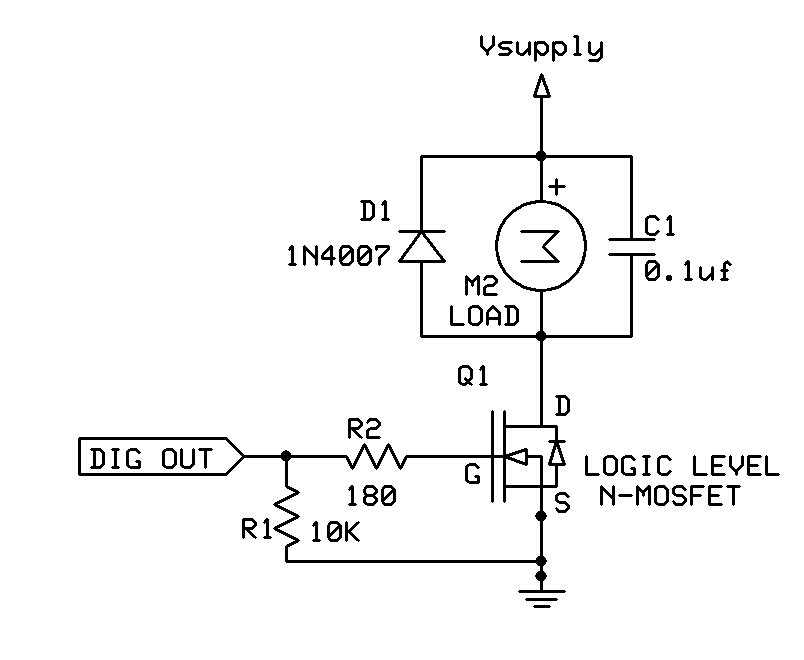
For simple on/off control a suitable logic level MOSFET or DC Solid State Relay would be a better choice. An inductive kick suppression diode is required, as shown below:
I would strongly recommend using a DC SSR instead.
It is very dangerous to mix high (50V or greater) and low (3.3 or 5V) voltages. But if you insist on using a MOSFET,
Make sure it is rated for 200V or higher drain voltage, and at least twice the maximum current required by the load.
Use a custom PCB, NOT a breadboard, as the breadboard connectors will burn.
Use an optocoupler to isolate the gate connection from the Arduino, otherwise you might fry the Arduino, your computer, and yourself in one short and violent event.
Example circuit below (the details will all be different):
Don't run the 90V supply to the relay board / circuit.
Just run sketch with the arduino connected to the relay board, listening to how the relay goes click-clack (or not). Maybe increase time to 1 sec or more.
Yeah I messed up with this(the relay). I read the specs further, turns out (well, I believe) it can handle both AC and DC but DC's up to 30 volts. I think I'll test another relay and see if it works at 24 volts.