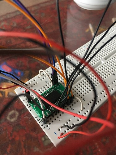
Dear community,
I'm new to Arduino and considering this I'm working on quite an ambitious project. I would like to turn a harp sculpture into an instrument with capacitive touch sensors.
I found a code by Esperienze Elettroniche for Arduino UNO with which you can turn any metal object into a capacitive sensor with just one analog pin. It works perfectly fine! As you need A0 as a pull-up resistor there's 5 pins left to turn into sensors. I would like to have more touch sensors though, so I built a 16-channel Multiplexor similar to the CD74HC4067.
I found out how to connect the MUX to the Arduino by connecting S0-S4 to digital pins 8-11, GND to GND, VCC to 5V and SIG to A1 and an according code. I don't know how to combine those two codes though in order to let the touch sensor code run through the MUX so to say..
Here's Esperienze Elettroniche's touch sensor code combined with a code I found on hooking up a MUX with Arduino. It gives me many errors ![]() I thought I could assign A1 to all of the touch sensors as this is where the MUX's SIG connects with the Arduino, does that make sense or does that confuse the program?
I thought I could assign A1 to all of the touch sensors as this is where the MUX's SIG connects with the Arduino, does that make sense or does that confuse the program?
#define THRES 200
#define SAMPLES 20

//Mux control pins
int s0 = 8;
int s1 = 9;
int s2 = 10;
int s3 = 11;

//Mux in "SIG" pin
int SIG_pin = A1;


struct touchPad {
  int pin;
  int unpValue;
  int value;
  char state = 0, prevState = 0;
  char toggleState = 0;
};

touchPad touchPad1, touchPad2, touchPad3, touchPad4, touchPad5;

void setup() {


  pinMode(s0, OUTPUT);
  pinMode(s1, OUTPUT);
  pinMode(s2, OUTPUT);
  pinMode(s3, OUTPUT);

  digitalWrite(s0, HIGH);
  digitalWrite(s1, HIGH);
  digitalWrite(s2, HIGH);
  digitalWrite(s3, HIGH);

  Serial.begin(57600);


/* Set A0 pull-up resistor, used to charge internal capacitor */
pinMode(A0, INPUT_PULLUP);
analogRead(A0);


/* Initialize sensors */
touchPadInit(&touchPad1, A1);
touchPadInit(&touchPad2, A1);
touchPadInit(&touchPad3, A1);
touchPadInit(&touchPad4, A1);
touchPadInit(&touchPad5, A1);


Serial.begin(57600);


}

void loop() {

  //Loop through and read all 16 values
  for (int i = 0; i < 16; i ++) {
    //  Serial.print("Value at channel ");
    //Serial.print(i);
    //Serial.print("is : ");
    Serial.println(readMux(i));
    delay(1000);
  }


float readMux(int channel) {
  int controlPin[] = {s0, s1, s2, s3};

  int muxChannel[16][4] = {
    {0, 0, 0, 0}, //channel 0
    {1, 0, 0, 0}, //channel 1
    {0, 1, 0, 0}, //channel 2
    {1, 1, 0, 0}, //channel 3
    {0, 0, 1, 0}, //channel 4
    {1, 0, 1, 0}, //channel 5
    {0, 1, 1, 0}, //channel 6
    {1, 1, 1, 0}, //channel 7
    {0, 0, 0, 1}, //channel 8
    {1, 0, 0, 1}, //channel 9
    {0, 1, 0, 1}, //channel 10
    {1, 1, 0, 1}, //channel 11
    {0, 0, 1, 1}, //channel 12
    {1, 0, 1, 1}, //channel 13
    {0, 1, 1, 1}, //channel 14
    {1, 1, 1, 1} //channel 15
  };

  //loop through the 4 sig
  for (int i = 0; i < 4; i ++) {
    digitalWrite(controlPin[i], muxChannel[channel][i]);
  }

  //read the value at the SIG pin
  int val = analogRead(SIG_pin);

  //return the value
  // float voltage = (val * 5.0) / 1024.0;
  // return voltage;


/* setMuxChannel (1);
  int val = analogRead (muxSIG);
  Serial.println(val);


  /* Scan sensors */
touchPadScan(&touchPad1);
  touchPadScan(&touchPad2);
  touchPadScan(&touchPad3);
  touchPadScan(&touchPad4);
  touchPadScan(&touchPad5);


  Serial.print(touchPad1.value);
  Serial.print("\t");
  Serial.print(touchPad2.value);
  Serial.print("\t");
  Serial.print(touchPad3.value);
  Serial.print("\t");
  Serial.print(touchPad4.value);
  Serial.print("\t");
  Serial.println(touchPad5.value);
  Serial.print(" ");


  delay (100);

}


void touchPadInit(touchPad *pad, int pin) {
  pad->pin = pin;
  pad->unpValue = (sampleB(pin) - sampleA(pin));
  DIDR0 |= 1;
  DIDR0 |= 1 << (pin - A0);
}

int sampleA(int sensePin) {
  /* Sample capacitor is charged to VCC
     via A0 pull-up resistor, touch pad
     is discharged by pulling pin low
  */
  ADMUX = 0b01000000;
  pinMode(sensePin, OUTPUT);
  digitalWrite(sensePin, 0);

  pinMode(sensePin, INPUT);
  ADMUX = 0b01000000 | sensePin - A0;

  ADCSRA |= 1 << ADSC;
  while ((ADCSRA & (1 << ADSC)) != 0);

  return ADC;
}

int sampleB(int sensePin) {
  /* Sample capacitor is discharged by selecting
     GND as ADC input, touch pad is charged to VCC
     via pin pull-up resistor
  */
  ADMUX = 0b01001111;
  pinMode(sensePin, INPUT_PULLUP);

  pinMode(sensePin, INPUT);
  ADMUX = 0b01000000 | sensePin - A0;

  ADCSRA |= 1 << ADSC;
  while ((ADCSRA & (1 << ADSC)) != 0);

  return ADC;
}

void touchPadScan(touchPad *pad) {
  static float A, B;

  A = 0;
  B = 0;

  /* Get some readings from sensor and calculate average */
  for (int i = 0; i < SAMPLES; i++) {
    A += sampleA(pad->pin);
    B += sampleB(pad->pin);
  }

  A /= SAMPLES;
  B /= SAMPLES;

  pad->value = (B - A);

  /* Member unpValue is a running average of the unpressed readings.
     A sudden change in sensor reading is interpreted as a touch
  */
  if (pad->value > (pad->unpValue + THRES))
    pad->state = 1;
  else {
    pad->state = 0;
    pad->unpValue = ((float)pad->unpValue * 0.9) + ((float)pad->value * 0.1);
  }

  if (pad->state == 1 && pad->prevState == 0)
    pad->toggleState = !pad->toggleState;

  pad->prevState = pad->state;
}
Attached you'll also find a picture of MUX setup. I put 5 black wires for sensors in I1, I2, I3, I4 and I5 (pins 4-8 on the MUX). Thanks a lot for any hint!
Best wishes, Elena
