Hi everyone,
I'm working on a Shuttle Board 3.0 BMI323 associated with an Arduino Uno R3, you will find attached the code I'm using in order to use it.
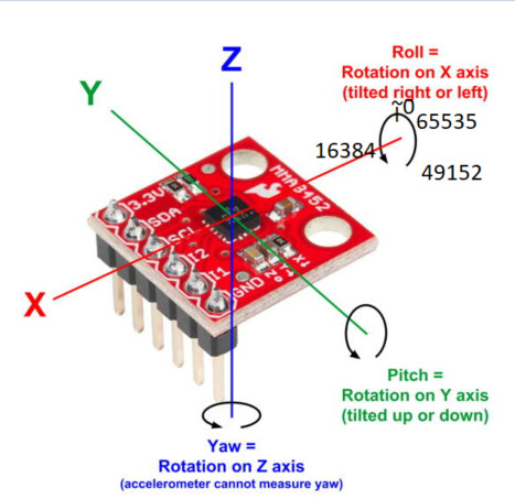
My goal is to measure an angle in degree by getting X, Y and Z axis.
I'm communicating with the BMI323 by I²C. Only the SDI/SDA, SCK/SCL, VDD, VDDIO and GND are connected to the arduino. It's running in 3.3V and there is a 5V/3.3V I²C converter and the resault are:
As you can see, the problem is that I have 0 in X axis and my temperature (in °C) is way too high and irregular (aswell as gyr_y and gyr_z that are irregular).
I suggest to scan for its address and put a test on its address in setup().
Don't set the I2C bus to 400kHz, use the default.
Wire.beginTransmission(0x69)
int n = Wire.endTransmission():
if( n == 0)
  Serial.println( "sensor found at 0x69");
else
  Serial.println( "Where is it ?");
Then try to read the CHIPID from register address 0.
Can you pull SDO with a resistor to GND ? I can not read in the datasheet that it is allowed to leave it not connected.
Please show a photo that shows how the I2C level converted is wired. Did you apply both 5V and 3.3V to it ?
Ok sorry, I'll do it in my next posts.
So, I've put a 1k ohms resistor from SDO to the GND.
Now the address has changed has the doc says:
"The default I²C legacy address of the device is 7h’0b1101000 (0x68). It is used if the SDO pin is pulled to ’GND’. The alternative address 7h’0b1101001 (0x69) is selected by pulling the SDO pin to ’VDDIO’."
Citation
Wire.beginTransmission(0x69)
int n = Wire.endTransmission():
if( n == 0)
Serial.println( "sensor found at 0x69");
else
Serial.println( "Where is it ?");
I've tried your code by adapted it with 0x68 and it find my sensor.
I'm using defaut bus frequency now.
I'm trying to read ChipID but it return 0:
Can you write down the code to read the register ?
A register address is 8 bits ? and the registers are 16 bits ?
Wire.beginTransmission(0x68);  // I2C address
Wire.write(0x00);              // register address 0x00
int error = Wire.endTransmission();
if( error == 0)
  Serial.println( "register selected");
else
  Serial.println( "No no no no");

int n = Wire.requestFrom( 0x68, 2);
if( n == 2)
{
  Serial.println("Got 2");
  int data1 = Wire.read();
  int data2 = Wire.read();
  Serial.println( data1, HEX);
  Serial.println( data2, HEX);
}
else
{
  Serial.println("Ouch, that hurts");
}
Please show your sketch that you use to run the test with.
Do you have a (USB) Logic Analyzer ? I'm a fan of the LHT00SU1. Combined with sigrok/PulseView it can decode the I2C signals. The analog channel has to be turned off for a higher sampling rate of the digital signals and the 48MHz sampling rate is not exactly 48MHz.
//Read data in 16 bits
uint16_t readRegister16(uint16_t reg) {
  Wire.beginTransmission(INC_ADDRESS);
  Wire.write(reg);
  Wire.endTransmission(false);
  Wire.requestFrom(INC_ADDRESS, 2);
  uint16_t data[20];
  int i =0;
  while(Wire.available()){
    data[i] = Wire.read();
    i++;
  }
  return (data[0]   | (uint16_t)data[1] << 8);
}
Yes, the register address is 8 bits and it return 16 bits value.
Your code return me:
register selected
Got 2
0
0
Also, I've tried an I²C scanner and here are the code and the result:
#include <Wire.h>
void setup()
{
  Wire.begin();
  Serial.begin(115200);
  while (!Serial);
}
void loop()
{
  byte error, address;
  int nDevices;
  Serial.println("Scanning...");
  nDevices = 0;
  for(address = 1; address < 127; address++ )
  {
    // The i2c_scanner uses the return value of
    // the Write.endTransmisstion to see if
    // a device did acknowledge to the address.
    Wire.beginTransmission(address);
    error = Wire.endTransmission();

    if (error == 0)
    {
      Serial.print("I2C device found at address 0x");
      if (address<16)
        Serial.print("0");
      Serial.print(address,HEX);
      Serial.println("  !");

      nDevices++;
    }
    else if (error==4)
    {
      Serial.print("Unknown error at address 0x");
      if (address<16)
        Serial.print("0");
      Serial.println(address,HEX);
    }
  }
  if (nDevices == 0)
    Serial.println("No I2C devices found\n");
  else
    Serial.println("done\n");
  delay(5000);           // wait 5 seconds for next scan
}
Scanning...
I2C device found at address 0x68 !
I2C device found at address 0x7E !
done
According with doc, the 0x7E is the CMD command, wich is used to configure the device before running it:
A I2C decoder of the signals on your computer is a great advantage.
This is a result:
register selected
Got 2
0
0
But can you show the exact sketch that gave that result ?
It found I2C address 0x7E, that is weird. The CMD command register has register address 0x7E, that is not the I2C address.
There is either someone else on the I2C bus, or the I2C bus is so weak, that 0x7E gives an ACK somehow. It might indicate that there is something wrong with the I2C level shifter. Do you have a 3.3V board ? Do you use a module for the level shifting or did you make it yourself with components ? You could test your level shifter with a multimeter and switch SDA and SCL between INPUT and OUTPUT LOW, each for 2 seconds or so.
I've tried with an Arduino Nano 33 BLE hich works in 3.3V, so without my level shifter. With my scanner address, I found only one address, which is good and which means that my homemade level shifter has a problem somewhere... Here is the output of the scanner:
Scanning...
I2C device found at address 0x68 !
done
However, It still found nothing in X axis and other data is very unstable
Please remove everything that is not needed, the softReset, the writeRegister, the readRegister, everything.
Read the CHIP_ID and do nothing else that might mess up the chip.
If your can read the CHIP_ID, then I would like to read the temperature.
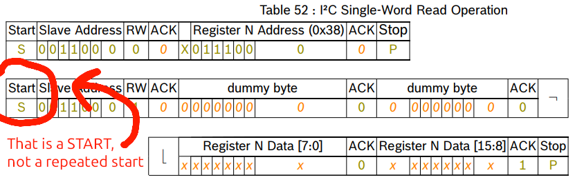
And without the repeated start ? Can you remove the 'false' parameter ?
The datasheet has a mistake, they say that 'S' is a repeated start, but 'S' is always a normal start.
Could you also add a delay of 1 second after 'Wire.begin()' ?
Your code still has the 'false' parameter for Wire.endTransmission(). Did you try without 'false' and reading 4 bytes ?
The 'true' for the third parameter of Wire.requestFrom() is never used, you may remove that.
Did you see the 'START' in the picture:
Dummy bytes ? I missed that when looking at the datasheet Sorry.
O, they don't always show them: "For simplicity the dummy bytes are not shown in the examples below".
So yes, for I2C, there are two dummy bytes. They are zero. Reading zero for the first two bytes was correct all along.
Did you get 4 bytes and they all were zero ?
As far as I understand it, after a soft-reset or after a power-up, the registers can be read. It should be possible to read the CHIP_ID. Can you power down the Arduino board and capture the 4 bytes when applying power for the first time ? You could blink a led when one of the four bytes is not zero.
In a normal situation, a chip could be in sleep mode or could be broken or the chip is not according to the I2C standard with its timing. I'm out of ideas what to try
Meanwhile, I have been reading about I3C. Every I3C sensor should ACK the broadcast address 0x7E. If there are ten I3C sensors, then all ten should ACK. I'm not sure if the I2C Scanner can put a sensor in I3C mode, so it is best to stay away from the I2C address 0x7E.
I've still have an issue
My problem is when I read X, Y or Z axis, the return value sould be between 0 and 65535 (2^16). But my usable range is from 49152 to 16384 (around 2^15), the other part (from 16385 to 49151) is never returned, do you know why ? Here is my last version of readAxis:
I count 14 bytes (plus 2 dummies makes 16), why do you read 20 ?
The register map is in the datasheet "Table 35", page 63, 64.
The I2C data (page 222, 223) shows that the lowest byte is send first.
The acc_x is 16 bits, is that unsigned ? That would be a 'uint16_t' variable. The Wire library uses bytes, each Wire.read() returns a byte.
So, grab a byte, put it in the lower byte of the 'uint16_t', grab another byte and put it in the higher byte.
If there is a problem with the sensor or the I2C bus, then the Wire.read() could return -1. Therefor I would like to check if all the bytes have been received, to be sure that Wire.read() does not return -1.
When 16 bytes are requested and 16 bytes are received then there is no need for 'Wire.available()', because it is known how many bytes there are.
void readAllAccel()
{
  Wire.beginTransmission(INC_ADDRESS);
  Wire.write(0x03);
  int error = Wire.endTransmission();    // checking for an error could be added

  int n = Wire.requestFrom(INC_ADDRESS, 16);   // 7 registers, each 16 bits, plus 2 dummy bytes
  if( n == 16)                                 // the I2C transaction was a success ?
  {
    // Get rid of those stinking dummy bytes
    Wire.read();
    Wire.read();

    // 7 values from the sensor (each 16 bits)
    uint16_t data[7];
    for( i=0; i<7; i++)
    {
      data[i] = (uint16_t) Wire.read();           // first byte is lowest byte
      data[i] |= ((uint16_t) Wire.read()) << 8;   // second byte is highest byte
    }
    x = data[0];
    y = data[1];
    z = data[2];
    gyr_x = data[3];
    gyr_y = data[4];
    gyr_z = data[5];
    temperature = data[6];
  }
}
Instead of separate variables, you could work with arrays in the sketch. For example an array for the acceleration and an array for the gyro, or everything combined in a single array.
The function "readAllAccel()" should be a general function to read a number of registers and store them in an array of course
Looking once more at your code, it should work. You can see my previous post as my interpretation.
Then the sensor output is limited. Maybe the raw data has a certain range.
Can you explain about the range. Is the lowest value 16384 and the highest value 49152 ?
When the accelero is flat positionned, I've got around 0, when I turn it to the left, it rise until 16384 and on right, it goes directly from 65535 until 49152 (I hope I'm clear enougth, here is a schematic...)