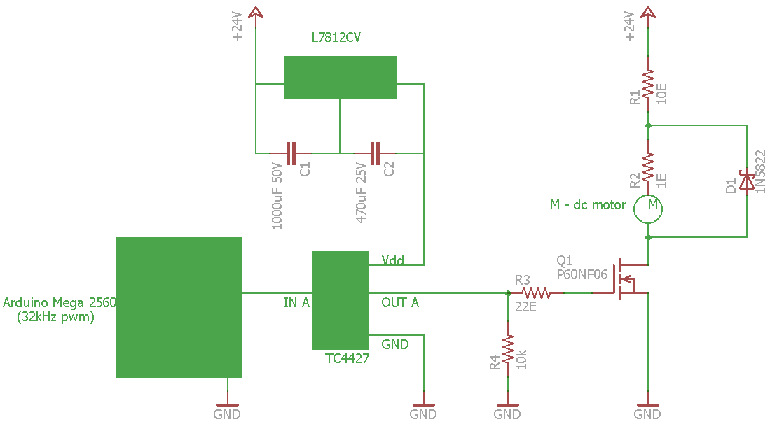
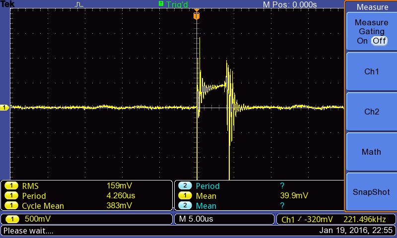
im using DCX22L EB KL 24V - Maxon dc motor. There is a need for stalling the dc motor in my application. I'm a mechanical engg student, with limited electronics knowledge. i tried a circuit(attached below) using mosfet n arduino to control the motor torque by varying the duty cycle of PWM(30KHz). The voltage variation across the dc motor is measured using oscilloscope across a shunt resistor as shown in fig. and oscilloscope image is also attached.
Is there any problem with the circuit because its showing lot of fluctuation ?
Please give suggestion to remove this fluctuation
thanks in advance
Fail1: You have probably fried your Arduino's output pin if that resistor to ground really is 10 ohms.
Fail2: You are not using a logic-level MOSFET.
Fail3: You are trying to do fast PWM without a gate driver chip.
With fast PWM (you say 30kHz) you must use a proper MOSFET gate driver, you cannot
get away with driving it direct from the Arduino. There are 1000's of low-side gate driver
chips to choose from alas, I've used the MIC4420 and MIC4422 before, they can drive
huge MOSFETs and are overkill. Read the datasheet.
That motor has 7.25 ohm windings and a continuous power limit of 20W (with heatsinking),
so you have to be aware of that if running at the stall point. At 24V full drive it pulls 24*24/7.25 = 80W,
so you can't stall it at full drive for long or it will be destroyed.
If you want to drive the MOSFET direct from the Arduino you will need:
150 ohms between Arduino pin and gate (so you don't over-current the pin),
10k from gate to source (to switch it off during reset).
You must stick to a few kHz max for PWM or you'll simply cook the MOSFET
with this low current gate drive.
You need a logic level MOSFET.
Oh, the other thing, no decoupling on the 24V rail? 220uF 33V or better would be a start, kill off
most of the ringing.
Its also recommended to add a small amount of ceramic capacitance direct across the motor windings to
reduce spark-noise (1 to 10nF or so) - that's not going to change the behaviour, just be kind to nearby
radios.
At the industrial level dc motors are frequently used in the stalled condition and are also frequently used with a speed imposed by the mechanical load and run at a controlled torque. To do this a current regulator is used which controls the current and so the torque.
Of course you have to look at a few things such as ventilation and commutation capability. If the motor is self cooled (by an internal fan) the ventilation disappears at standstill so it may overheat when stalled. The cure for this is external ventilation. If the motor is stalled at high current the commutator bars under the brushes will probably overheat. The cure for this is a super large commutator. Torque motors of any substantial size are normally designed for the application.
As a current controlled motor will run away if it loses its load an over riding speed regulator is normally provided just to keep the speed under control on a runaway.
Looking at the pictures, the scope is connected to read current and is simply showing a lot of ringing when the current is turned off or on. I would experiment with an RC snubber across the motor. This is simply a series resistor and capacitor, say 100 ohms and a few microfarads. This requires trial and error and the idea is to change the ringing into heat.
Unless a motor is designed for stall operation it will cook if stalled at full supply voltage - the ratio
from stall to operating current is large, and the heat generated goes as the square of current.
MarkT
If you are using a motor stalled, or with speed imposed by the load you must use a current regulator to control the current and make no attempt to control it via the voltage. The current regulator will hold the current at full load or less and if you got in with a meter and measured the terminal voltage you would find it low, equal to the armature IR drop.
This is used all the time in metal rolling between stands where the motor forces a looper up under the strip with enough force to hold the required tension and just sits there producing torque but no speed. It also shows up in coilers where the strip speed is set by the preceding sections of the mill and the motor is in current control mode to hold constant tension as it winds up the strip. Of course in this case the motor voltage varies with speed but it is not directly controlled.
Depends on the industry you are dealing with. When I worked in this line for a living it was perfectly normal to refer to "stalled" and this always assumed current control.
Further to my reply to MarkT--- The situation of full voltage and stalled implies something has gone badly wrong with the control. To cater to this you normally supply an instantaneous overcurrent relay, usually abbreviated to IOC relay to trip off for protection. The drives we supplied for general use were usually set for 150% current limit and the motor was good for a short time at this current then if necessary a time delay trip off. I did one for 225% current limit but this was for a calculated duty cycle type application. It was pretty big-- the 225% came out to 17,170 amps.
In another case with the standard 150% CL the motor would stall when some ice got into the works; the solution to that was 300% CL for 2 or 3 seconds to break the ice then back to the standard 150%
I hope this clarifies the normal industrial practice a little bit.
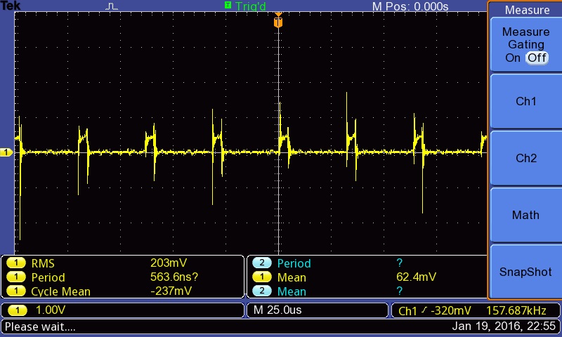
thanku guys for valuable information, i modified the circuit as the attached one,
previously i try to us oscilloscope across the resistor outside the motor loop,(see previous post)
In new circuit i put oscilloscope on the resistor series to motor in the loop( resistor, motor, flywheel diode), it shows continuous current waveform as expected.
But the current Issue, when i burn the code in arduino, motor speed suddenly increase and then decrease to slower speed corresponding duty-cycle (even for very low duty-cyle "analogwrite(pin,1) ")
How to solve this issue, i want to run motor at corresponding duty-cycle without sudden increase in speed at burning the code.
![IMAG1214[1].jpg](https://europe1.discourse-cdn.com/arduino/original/3X/9/a/9ae1ec867b468196667dcbfce3dc226716b60cc6.jpg)