Dear Forum,
As always thank you for your assistance thus far. I am back with yet another question which I hope you can help me solve. I am working on my PhD project which is using an Arduino Mega, a variety of sensors , an ESP8266-01 WiFi module as well as a DFRobot Mini Player. I have to power my system using LiON batteries since my deployment is in a rural area in South Africa . I have the following as a power solution:
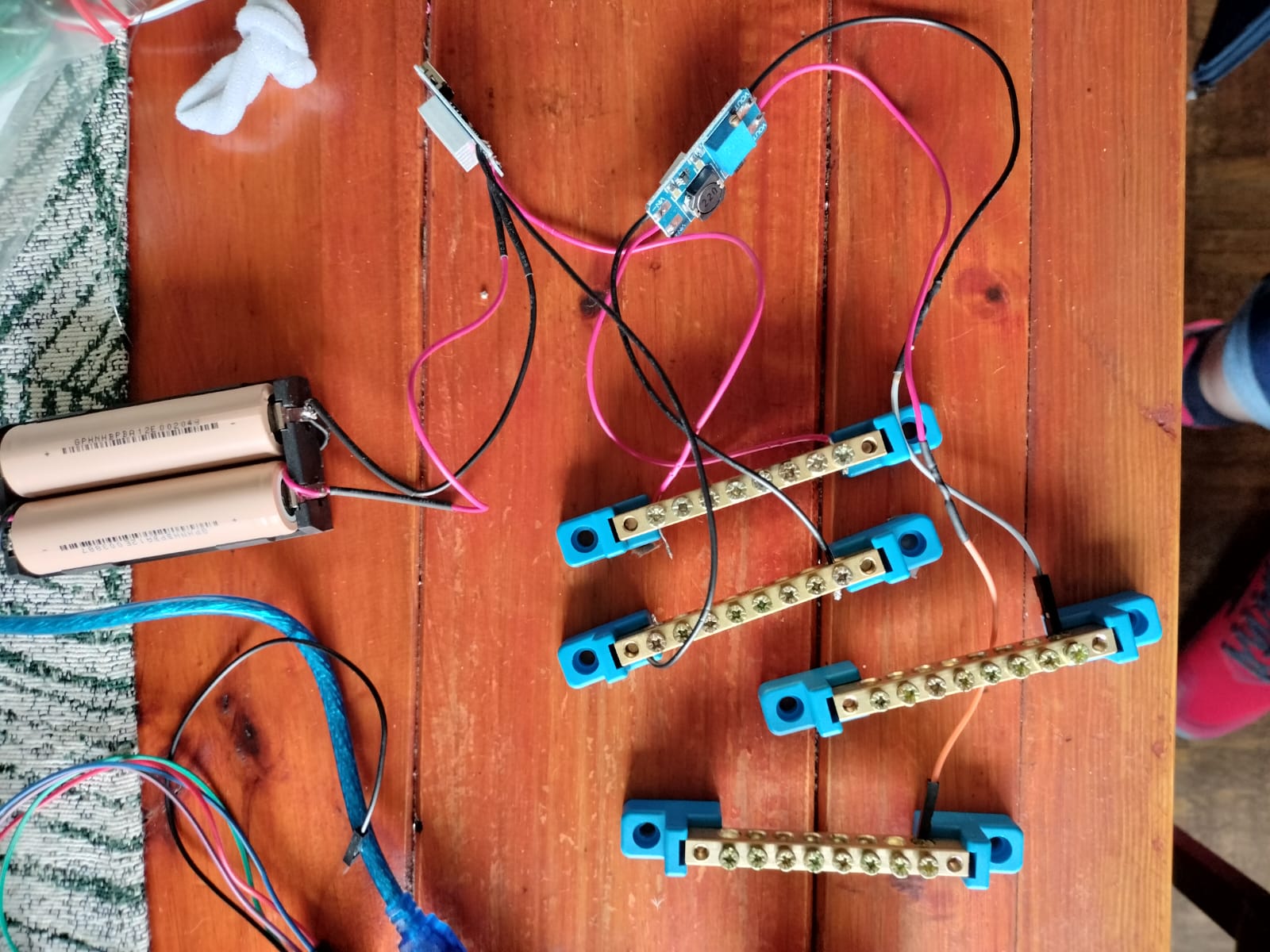
2 18650 4.2 V LiON batteries soldered in parallel. The batteries connect to a TP4056 LiON charging module which connects to a busbar. From there I connect to a MT3608 dc-dc boost module (T3608 based DC-DC Step-up Boost Adjustable Module Input 2-24V Output 5-28V Max. 2A Max output current. ) to step the voltage up to 5v . All the sensors work fine but both the DFRobot Mini player and the ESP do not work when they get their power from the battery source but works fine when powered from the Arduino. Should I perhaps add a voltage regulator to keep the volts and current more stable ? I can only power one from the board and really need both. Any advice will be highly appreciated.
Hi Railroader, thank you so much for your reply. I am not great at electronics, I can try. What schematics do you need. Just how I am connecting everything ?
Hi Again and thank you for helping !
I have drawn a very simple diagram. From what I have read online (DFRobot Docs) the miniplayer use 20mAh and either 3.3 or 5V.
The circuit works IF - I power the Arduino board using the Vin port using the 5v coming from the MT3608 boost board. I can then connect the miniplayer directly to the 5v and GND on the Arduino board and it works perfectly.
The circuit does NOT work if I connect the VCC and GND of the miniplayer to the MT3608 or just directly to the batteries. I am a bit perplexed. I do agree that it is something to do with the power but I cannot figure out what and need help. I need to finish my PhD before it finishes me I have learned so much from this forum (thank you)
I need to power the DFMini player and an ESP8266-01 - both work fine from the 5v /3.3.v on the arduino but not the power pack.
the best setup for this should be, connect the output from the MT3608 to 5v on the Mega, and connect the esp-01 to the 3.3v of the Mega, (this is your only reliable 3.3v source) and make sure there is common GND, and leave the USB cable disconnected. also connect the DF player to 5v & GND.
Your schematic hardly clarifies anything. I don't need to see what the parts look like i need to see what pins are connected to what.
DFRobot -------------- Arduino
GND ----------------------GND
VCC ------------------------VCC
RX---------------------------tx2(16)
TX---------------------------rx2(17)
(I am using Serial 2)
For the ESP-01 I need to connect the EN pin to VCC aswell - any advice ?
Yes of course you do, , and there should be a voltage divider on the ESP rxpin (droppin the 5v logic to 3.3v) if you intend to connect thru the UART. I always connect VCC, CH_PD & RST to 3.3v GND to GND.
ESP TX to Mega RX and Mega TX -> 1K -> ESP-rx -> 1K -> 1K -> GND. and make sure that GPIO 0 & 2 are not pulled LOW.
LOL I did state it might be a silly question - I did not even think about splitting out from the board itself. It all works now. Can I please come ask some more really really stupid questions as I go along ?
In future, supply a circuit diagram, saves a book and a half of explanations and shows exactly what you have.
Fritzing is next to useless, so don't use it.
Easy to decypher and form opinions on what might be going on.
They've been used for this purpose for a gazillion years now, so try it.