The motor draws 100 mA at 3.3 V so I figured I cannot directly power it from a digital out pin, but need to use a separate power supply, switched by a transistor.
A Teensy digital out is connected to the gate of the transistor (through a 1kOhm resistor).
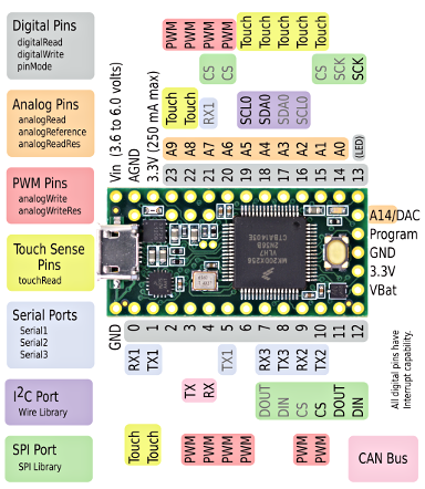
One lead of the motor is connected to 3.3V (supplied from USB via the Teensy 3.3V pin, which is 250mA max in the Teensy 3.2).
The other lead of the motor is connected to the drain of the transistor.
The source of the transistor is connected to ground.
Now my thinking is that setting the digital out HIGH should make the transistor conductive and turn the motor on. I wrote a sketch that switches the pin on and off once a second. When I put an LED in place of the motor, the LED blinks as expected. But with the motor, it doesn't work -- it just stays off. Of course, I've checked that the motor works when directly connected to the 3.3V. I've tried all sorts of other configurations, and I've tried several transistors in case I had blown one up. The transistors also pass this test.
ricky101:
Not the best way to power a motor via the micro board.
Most motors have a large start current that may well blow the Teensy, particularly if stopping and starting a motor repeatedly every second.
The Mosfet needs to be a logic level type, probably the Teensys output is too low to turn on that mosfet enough to let the 100ma through.
Search the forum and you will find similar posts where that Mosfet does not work and a logic level type is needed.
Thanks, that info helped! I guess I understand better now how the transistors work. Is my understanding correct that what you said can be read off the V_GS versus I_D plot in the data sheet? That suggests that the drain current is far below 100 mA even for a gate-to-source voltage of 4V. Consequently, the 3.3V of the Teensy won't be enough.
Regarding your statement that my approach would blow the Teensy: What would be a better approach? Split the power to the motor off before it goes into the Teensy rather than using the Teensy's 3.3V pin?
mjlm:
Regarding your statement that my approach would blow the Teensy: What would be a better approach? Split the power to the motor off before it goes into the Teensy rather than using the Teensy's 3.3V pin?
Yes, thats the way I would do it, as the motors current demand could be too much for the teensy regulator or cause a lot of electrical interference to the teensy chip
Just add a 3v3 regulator and caps from the +5v usb input or three 1A diodes would also work. ( .7+.7 +.2)
If you look in the big suppliers catalogues they have a sub section of Mosfets just for the logic level ones.
You probably do not need a regulator to power a (commutator-type) motor in the first place.
Just supply it from whatever power supply is already supplying the regulator, with a series resistor chosen to provide the correct voltage when the motor is running. This will limit the "stall" current and slow the motor's start-up which generally will not matter.
More strongly - if you are using a linear voltage regulator to power a motor, you don't understand
power electronics.... Power electronics is all about switch-mode (for that last 30 years or so), use
PWM to ramp up the drive to avoid large surge currents on switch-on.
One basic rule of thumb is never power any motor/servo/relay from a logic power supply rail, keep
inductive loads and high current loads away from delicate logic circuits if you want things to work
without drama!
3.3V logic MOSFETs are typically only available in surface-mount packages.
Have you considered a simple BJT for your 100mA motor? Even a 2N2222 should be enough for
that.