Using RX Pin of ESP-01 As Digital Input

Ok, I' want to start by saying that i've tried to google/CGPT answers until i'm blue in the face, and dumbed my code down to the point where i'm second-guessing myself at almost every point.

At it's most basic form, my watered down code should keep the RX pin of the ESP-01 low and read it's state as an input.

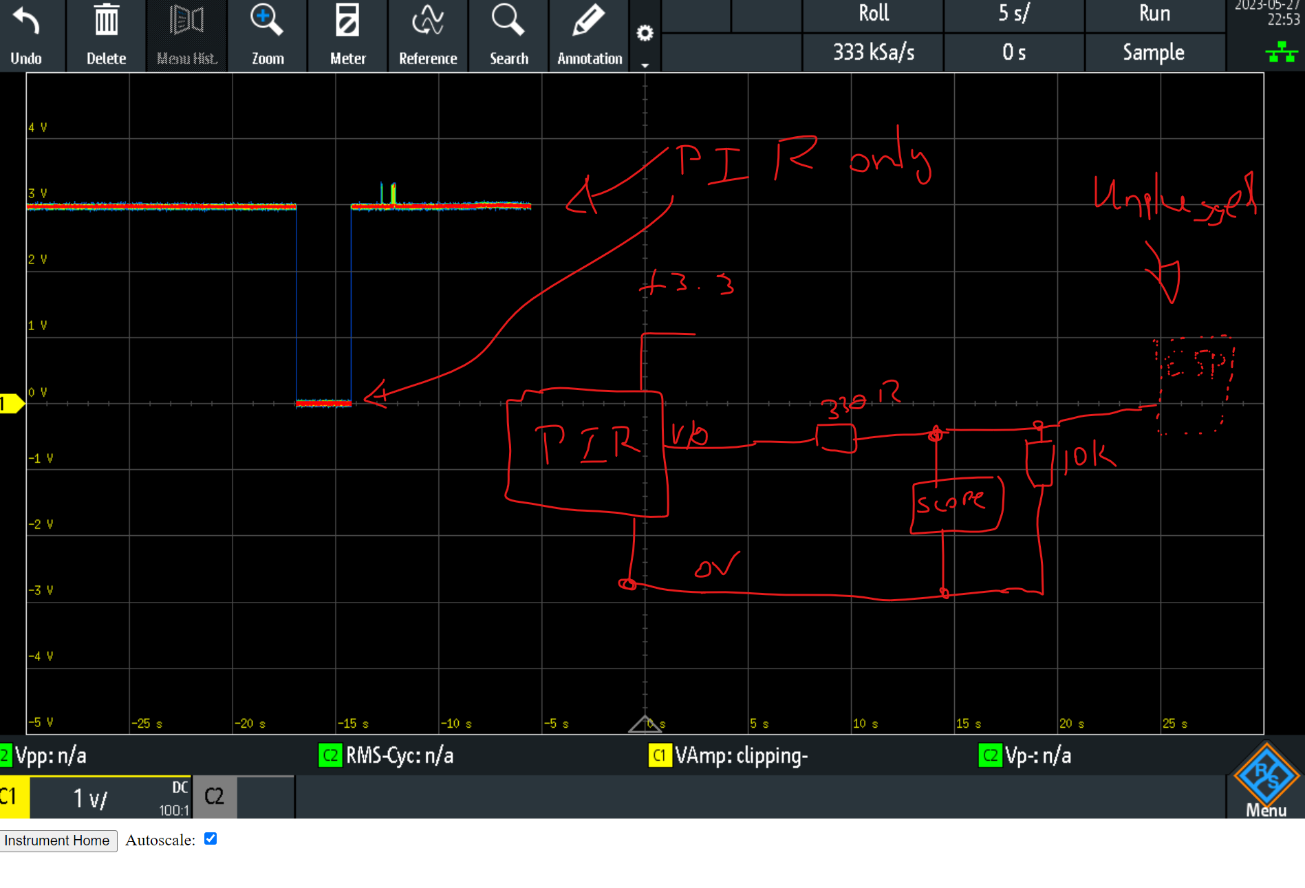
The schematic (very basic) is attached below.

I have been using this (HC-SR505) PIR sensor to output a 3.3V signal to the RX Pin of the ESP 01, using the ESP-01S DHT11 with the DHT11 sensor removed.

I have so far, put in series with the PIR sensor output and the RX pin input a 330R resistor + a pulldown resistor (10K) on the RX side of the micro, but the GPIO3 (RX) still decides to float to ~3VDC.

Removing the ESP-01 from the socket, proves that the PIR sensor is working while measuring on the RX pin from the ESP-01S DHT11 socket.

The following is my code:

const int switchPin1 = 3; // PIR Sensor on RX PIN

WiFiClient wifiClient;
PubSubClient client(MQTT_SERVER, MQTT_SERVER_PORT, callback, wifiClient);

void callback(char *topic, byte *payload, unsigned int length)
{

  // convert topic to string to make it easier to work with
  // String topicStr = topic;
  // EJ: Note:  the "topic" value gets overwritten everytime it receives confirmation (callback) message from MQTT

  // Print out some debugging info
  // Serial.println("Callback update.");
  // Serial.print("Topic: ");
  // Serial.println(topicStr);

  // EJ: copy and paste this whole else-if block, should you need to control more switches
}

// generate unique name from MAC addr
String macToStr(const uint8_t *mac)
{

  String result;

  for (int i = 0; i < 6; ++i)
  {
    result += String(mac[i], 16);

    if (i < 5)
    {
      result += ':';
    }
  }

  return result;
}
void reconnect()
{

  // attempt to connect to the wifi if connection is lost
  if (WiFi.status() != WL_CONNECTED)
  {
    // debug printing
    // Serial.print("Connecting to ");
    // Serial.println(ssid);

    // loop while we wait for connection
    while (WiFi.status() != WL_CONNECTED)
    {
      delay(500);
      //   Serial.print(".");
    }

    // print out some more debug once connected
    //  Serial.println("");
    //  Serial.println("WiFi connected");
    //  Serial.println("IP address: ");
    //  Serial.println(WiFi.localIP());
  }

  // make sure we are connected to WIFI before attemping to reconnect to MQTT
  if (WiFi.status() == WL_CONNECTED)
  {
    // Loop until we're reconnected to the MQTT server
    while (!client.connected())
    {
      //  Serial.print("Attempting MQTT connection...");

      // Generate client name based on MAC address and last 8 bits of microsecond counter
      String clientName;
      clientName += "esp8266-";
      uint8_t mac[6];
      WiFi.macAddress(mac);
      clientName += macToStr(mac);

      // if connected, subscribe to the topic(s) we want to be notified about
      // EJ: Delete "mqtt_username", and "mqtt_password" here if you are not using any
      if (client.connect(MQTT_CLIENT_ID, MQTT_USER, MQTT_PASSWORD)) // if (client.connect((char *)clientName.c_str()), MQTT_USER, MQTT_PASSWORD)
      {                                                             // EJ: Update accordingly with your MQTT account
        // Serial.print("\tMQTT Connected");
        client.subscribe(switchTopic1);
        // EJ: Do not forget to replicate the above line if you will have more than the above number of relay switches
      }

      // otherwise print failed for debugging
      else
      {
        // Serial.println("\tFailed.");
        abort();
      }
    }
  }
}

void updateOTA()
{

  // Port defaults to 8266
  ArduinoOTA.setPort(8266);

  // Hostname defaults to esp8266-[ChipID]
  ArduinoOTA.setHostname(MQTT_CLIENT_ID);

  // No authentication by default
  // ArduinoOTA.setPassword("admin");

  // Password can be set with it's md5 value as well
  // MD5(admin) = 21232f297a57a5a743894a0e4a801fc3
  // ArduinoOTA.setPasswordHash("21232f297a57a5a743894a0e4a801fc3");

  ArduinoOTA.onStart([]()
                     {
                       String type;
                       // client.publish(MQTT_CLIENT_DEBUG_TOPIC, "OTA Start");
                       if (ArduinoOTA.getCommand() == U_FLASH)
                       {
                         type = "sketch";
                       }
                       else
                       { // U_FS
                         type = "filesystem";
                       }

                       // NOTE: if updating FS this would be the place to unmount FS using FS.end()
                       // client.publish(MQTT_CLIENT_DEBUG_TOPIC, "Start updating");
                       // Serial.println("Start updating " + type);
                     });
  ArduinoOTA.onEnd([]()
                   {
                     // Serial.println("\nEnd");
                   });
  ArduinoOTA.onProgress([](unsigned int progress, unsigned int total)
                        {
                          // Serial.printf("Progress: %u%%\r", (progress / (total / 100)));
                        });
  ArduinoOTA.onError([](ota_error_t error)
                     {
    //Serial.printf("Error[%u]: ", error);
    if (error == OTA_AUTH_ERROR) 
    {
      //Serial.println("Auth Failed");
    }
     else if (error == OTA_BEGIN_ERROR)
      {
      //Serial.println("Begin Failed");
    }
     else if (error == OTA_CONNECT_ERROR)
    {
      //Serial.println("Connect Failed");
    } else if (error == OTA_RECEIVE_ERROR)
     {
      //Serial.println("Receive Failed");
    } 
    else if (error == OTA_END_ERROR)
     {
      //Serial.println("End Failed");
    } });
  ArduinoOTA.begin();
  // Serial.println("OTA update handler ready");
  // client.publish(MQTT_CLIENT_DEBUG_TOPIC, "OTA update handler ready");
}

void setup()
{
  pinMode(switchPin1, FUNCTION_3); // PIR Switch 1
  delay(10);                       // Delay after setting pin mode
  pinMode(switchPin1, INPUT);     // PIR Switch 1
  delay(10);
  digitalWrite(switchPin1, LOW); // Disabling internal pull-up

  // Start WiFi subsystem
  WiFi.mode(WIFI_STA);
  WiFi.begin(ssid, password);

  // Attempt to connect to the WiFi network and then connect to the MQTT server
  updateOTA();
  delay(100);
  reconnect();

  while (WiFi.status() != WL_CONNECTED)
  {
    delay(500);
  }

  delay(2000);
}

void loop()
{
  // reconnect if connection is lost
  if (!client.connected() && WiFi.status() == 3)
  {
    reconnect();
  }

  // maintain MQTT connection
  client.loop();

  //  MUST delay to allow ESP8266 WIFI functions to run
  delay(10);

  ArduinoOTA.handle();
}

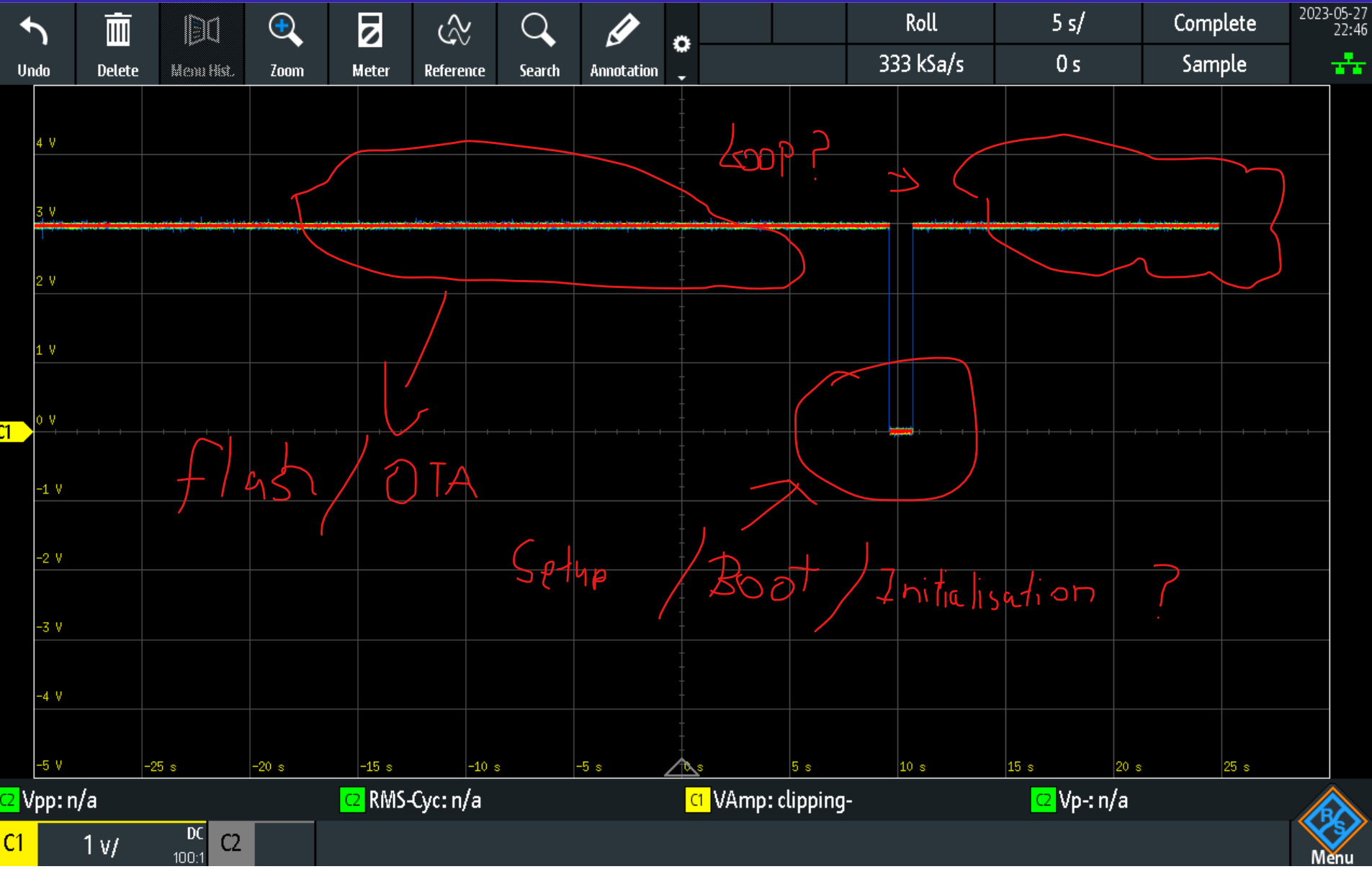
Please tell me that the ESP-01 will not disable the internal pullups when defining the GPIO pins as inputs? Or am i wrong by this assumption?

So I can eliminate all faults with the ESP-01 otuput being damaged, i also set it as an output and drove it low, i got about 0.5VDC.

If i force the GPIO pin to 0vdc with a 330R resistor (directly connected) it will register a LOW input.

Some reference links:
Link 1

Link 2

Hi, why double pinMode for the switchPin1 and what is FUNCTION_3 ?

Hey,

I've seen that just for those pins (TX/RX) you need to use that to tell it to use them as normal GPIO pins.

I will try again without.

Yup - Still the same! GPIO 3 (RX) Still high.

Have a look here Although, you are correct there is no need to re-set the pinMode, and the core automatically changes 'INPUT' to 'FUNCTION_3' for the GPIO pins that have 'FUNCTION_3' defined as 'INPUT' (which is basically all of the pins that have a FUNCTION_3) so there is no need. This table can be useful however if you want to switch between any of the other functions (like the UART or I2S) without using the standard functions to do so, which in this case is not applicable.

No by default they are set to INPUT, but once you call Serial.begin() they will switch to their UART connection, which for them is 'FUNCTION_0' , But some checking of the code shows that that has been removed.

The internal pullups are disabled by default, so unless you specifically enable them, they will be disabled. If you write the pin 'HIGH' and thereafter set the pin to INPUT, they will still be enabled, but again this does not apply.

Readable ! some connections are missing though. CH_PD needs to be pulled up for the ESP-01 to work, and with the exception of the RX-pin (GPIO 3) none of the other GPIO pins may be pulled LOW during boot to go into normal boot mode.

Just load an empty sketch onto the ESP, and add a weak pulldown (10K) resistor to GPIO 3 and it should measure 0v. If you do not add a pulldown or pullup resistor, with the pin will be in INPUT mode, it will technically be free-floating, and any measurement will not be relevant.

so just to recap.

pinMode(switchPin1, FUNCTION_3); // PIR Switch 1
  delay(10);                       // Delay after setting pin mode
  pinMode(switchPin1, INPUT);     // PIR Switch 1
  delay(10);
  digitalWrite(switchPin1, LOW); // Disabling internal pull-up

there is no need for any of this unless you switch the pin to a different mode somewhere, but even then a simple

pinMode(switchPin1, INPUT);

will suffice.

during boot, a short switching 'HIGH' of the pin does occur btw, and this goes for all exposed pins on the ESP-01, unfortunately this can't be helped, but it is only for 50-100 ms, so that is not what you are measuring.

Hey, thanks for all your replies, yup I have it sitting in that ESP-01S DHT11 PCB and it has all of the right logic levels to boot normally, and it does do that.

I'm able to flash OTA and also receive MQTT messaging of pin status.

See attached below - I've since got a scope onto GPIO3 and is confirmed at boot/just after I flash to go to 0VDC and then quickly back to high ~3VDC.

I have a feeling that another routine or function call might be trying to write to this pin, i wonder if it's worth changing switchPin1 to 0 or 2 just to see if they also remain high (as in no other function call is trying to write to TX/RX) ?

Also, yes, there is a 10k pulling GPIO3 to ground so, it sort of leads me to think that it might be really wanting to sit high for some reason? - I've confirmed again, with the ESP-01 unplugged, it still does all the right things (see attached below)

Please excuse my bad mouse-typing.

More disturbing that you can draw in only 1 color :wink:

well how about at the end of setup(), you call

digitalWrite(switchPin1, LOW);
pinMode(switchPin1, INPUT);

There shouldn't be anything pulling it HIGH, but there may be some debug part in the libraries that you use (which you have somehow omitted from you post) Also it would make your code a lot easier to read on this forum if you remove all commented out parts from it, so i don't spend time scrolling to find stuff.

Sorry, the stuff above that is just variable declaration/passwords for network etc.

These are the includes:

#include <PubSubClient.h>
#include <ESP8266WiFi.h>
#include <ArduinoOTA.h>

Noted RE the comments! I was thinking the same thing about the libraries, had a quick look to see but could not find anything obvious.

In hindsight I guess I could just scope the TX pin to see if anything is being sent!

Tried adding this:

digitalWrite(switchPin1, LOW);
pinMode(switchPin1, INPUT);

....And still the same! ><

I gave this a go (see below the whole setup routine), added a whopping 20,000ms delay between instructions at the end to see if something funny is going on, still had a flat trace sitting at 3V!

void setup()
{
  // start wifi subsystem
  WiFi.mode(WIFI_STA);
  WiFi.begin(ssid, password);
  // attempt to connect to the WIFI network and then connect to the MQTT server
  updateOTA();
  delay(100);
  reconnect();

  while (WiFi.status() != WL_CONNECTED)
  {
    delay(500);
  }
  delay(2000);

  client.publish(MQTT_CLIENT_DEBUG_TOPIC, "Setup Complete");
  PIR_State = digitalRead(switchPin1);
  // Convert the integer to a string
  String PIR_StateString = String(PIR_State);
  // Publish the string value
  client.publish(switchTopic1, PIR_StateString.c_str());

  digitalWrite(switchPin1, LOW);
  delay(20000); // Crazy long delay to see if anything is holding it up
  pinMode(switchPin1, INPUT);
  delay(20000); // Crazy long delay to see if anything is holding it up
}

Will give it a go with another micro+board+blank code without anything fancy (no wifi/OTA/MQTT stuff)

As a side note, I do recall many years ago when I was doing a lot of dev work on the mega8's I recall the delay function stopping the processor so I avoided it like the plague, now that I'm back trying this 'new' (to me) arduino platform I note that it is back and is used quite a lot.

I doesn't 'stop the processor' it just holds the linear execution of the program, interrupts still work, and in case of an ESP, scheduled tasks get executed, and the wdt gets reset, (basically it calls yield() )
but if it can be done without that is of course still usually better.

Tomorrow i will see if i can re-create your issue, because this doesn't sound right. I rarely use GPIO 3 as an INPUT (unless as part of the UART) , but testing should not be hard.

1 Like

ZZZZ sleep well!

SO! I watered everything well down, got RX pin to come down low enough and to have the ESP do something when it detects a logic change.

HOWEVER, what's weird is that the Tx outputs a pulse train when I drive it high (see code, I used LED attached to it to signal PIR input status).

So, here are a couple of colours, hopefully you'll like that more haha - PIR is the Green trace (C2) and the Tx pin is the Yellow trace (C1).

Code:

#include <Arduino.h>

const int switchPin1 = 3; // PIR Sensor on RX PIN
const int TxPin = 1;      // Indicate with Blue Tx LED

void setup()
{
  pinMode(switchPin1, INPUT);
  pinMode(TxPin, OUTPUT);
}

void loop()
{
  if (digitalRead(switchPin1))
  {
    digitalWrite(TxPin, HIGH);
  }

  else
  {
    digitalWrite(TxPin, LOW);
  }
  delay(10);
}

Traces:

Next I'll load up more of the old code and see at which point RX remains high - I will report back, hopefully I'll be able to find the culprit library/routine.

Wow - what a long thread for such a simple issue, so far, i've narrowed this down to the following line: WiFi.mode(WIFI_STA);

The weird pulse train I believe could be down to me, although I didn't take it further, all I did was to move the ESP-01 to the ESP-01s DHT11 PCB with the original modification with that PIR WITHOUT a 10K pulldown on the RX pin. This worked flawlessly - Had to reverse the logic on the digitalWrite routine to make the LED follow the PIR detection.

I'll update when I find where the WiFi.mode(WIFI_STA); opens the serial port.

Having a look around, i wonder if there's a build flag of sorts to disable all serial communications?

I saw this on PIO build flags (yes i'm using PIO) build_flags = -D DISABLE_SERIAL - This has failed to help though.

Found another routine from the Serial lib Serial.end(); - This also somewhat works depending on where you put it in the initialisation routine/setup but then what I would assume is some sort of timed routine/interrupt runs in the background it would just float the RX port back to ~3VDC.

..More to come....

This topic was automatically closed 180 days after the last reply. New replies are no longer allowed.