I need a vane anemometer for my project and I have a ruoshoi 816b digital anemometer. I want to use the sensor used in the device to send data to arduino for my project. I just can't find anything that might help me with my problem. Hoping someone could help.
Providing link to the data sheet for the sensor you want to use would be a first step in getting help.
Paul
Hi, @daydream0106
Welcome to the forum.
Please read the post at the start of any forum , entitled "How to use this Forum".
What model Arduino are you using?
As @Paul_KD7HB has asked some info on the sensor?
Can you please tell us your electronics, programming, arduino, hardware experience?
Thanks.. Tom... ![]()
![]()
![]()
![]()
trying to get data out of a portable device is hard unless the device has some sort of wired or wireless interface.
it would mean a very skilled person, hacking to the chip level and then decode the signals. way beyond all but the best hobbiests. I think the consensus would be to just make your own from the ground up.
if the hand held part is 100% self contained and the USB cable just sends data, then you might be able to get a USB analyzer and decipher the data on that line.
link to aliexpress ![]() https://www.aliexpress.com/item/32982569735.html
https://www.aliexpress.com/item/32982569735.html

From the website it appears the sensor can be unplugged from the digital counter.
I think the best way is to connect directly to the sensors. The air speed is likely a hall sensor providing pulses as the fan rotates. The temperature sensor is likely a 10K NTC resistor.
The first step is to disconnect the connector and count the wires.
As a guess I would expect 4 wires:
- Hall sensor power
- Hall sensor signal
- Hall sensor and temperature sensor ground
- Temperature sensor
You will need a multimeter and some connector parts to go any further.
RuoShui 816B Digital Anemometer Air Speed Sensor Measurement Temperature Velocity Wind Meter Speratue Vane Anemometro Windmeter|Speed Measuring Instruments| - AliExpress
this is the digital anemometer that I have. I only want the sensor part to send data to my arduino project but i can't find any source code for this matter. I also don't know if this is doable but looking inside the anemometer, it has 4 pins in the usb that can be connected to the arduino.
I am experience with arduino but only with sensors that the arduino library have. This is kind of new to me as there is no source code I can follow or guides for this matter.
yes it can be unplugged and inside the digital anemometer, there is a usb module that has 4 pins. Is there a way for the sensor to work if I plug the usb into a usb shield for the arduino to access the readings of the sensor?
Not following, You unplugged the senor from the digital "controller". Now where is the USB? Did you have to unplug the sensor to see the USB?
Photo...?
picture in post #4
the want connects to the body with a USB plug.
what is unknown is if the USB plug is a true USB serial link or just a 4 pin connector that uses the USB end connectors.
what is needed would be to use a scope and trace out the lines to see if they are on a SUB serial or if they are just digital, or analog pins.
Time to get out the Oscilloscope and start testing. no matter how you ask, we cannot know.
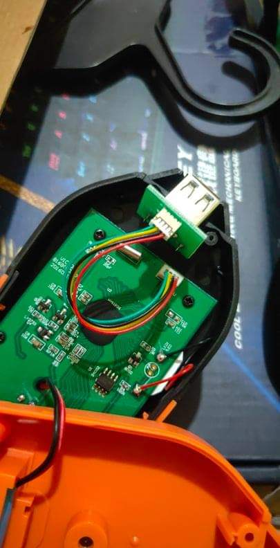
This is the inside of the digital anemometer. The sensor then connects to that port to send data to the to show in the digital anemometer.
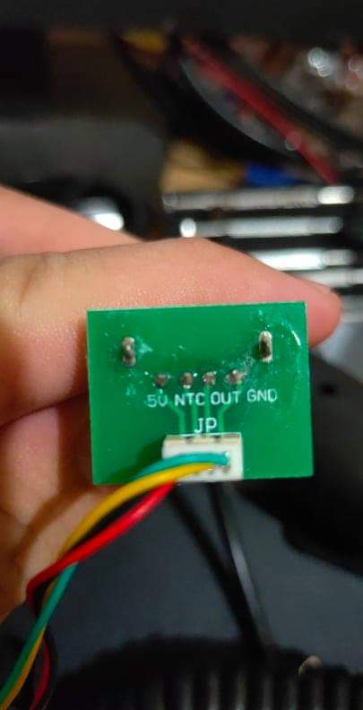
This is the labels for the usb port. Can I plug it into the arduino and read the data from the sensors?
Has the sensor been plugged into a computer to see if the sensor shows up as a drive?
If I had to guess, I would guess the NTC is a resistance or a voltage divider with one leg the NTC resistor. (NTC = Negative Temperature Coefficient Resistor).
The OUT would be pulses proportion to turns of the "propeller"
I just got the data from the output but it shows only 1023. 1023 is the maximum of the data it can get. 1023 is only .5 in the digital counter. Do I need a resistor so that I can get the right amount of data?
Need more information:
- What output are you trying to read?
- What input of the arduino are you using?
- How is the sensor wired?
- How is your code attempting to measure? (i.e. analog in, counter etc)
I'm trying to read the windspeed of the anemometer.
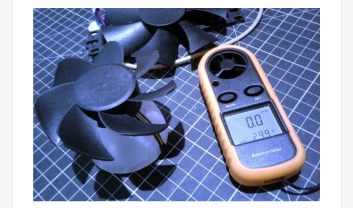
The sensor is wired with an 5v ,gnd , ntc and out. The arduino input I am using is analogRead. And for the coding i just simply put the 5v and gnd to it's corresponding pins and put the out in A0. I didn't put the ntc pin to anything because I just need the wind speed. After searching online for some similar peojects I found this schematic and I was thinking of it could be applied in my scenario since I also have 4 pins but the t1 and t2 is different. The anemometer he used is a BLDC cooling fan. See photo for reference for the schematic and the cooling fan.

This topic was automatically closed 120 days after the last reply. New replies are no longer allowed.