anarchy_1024:
And I saw the "not allowed", but wasn't that on the second example, not the third?
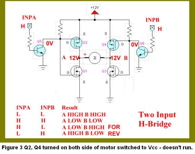
You're right, there are no "not allowed" states in circuit 3, but a problem arises as the drive signal to the MOSFETs swings through the centre - both the upper and lower MOSFET on each side will be turned partly 'on' for an instant, causing a partial short. (Both gates on each side will have 6V applied with a 12V supply.)
As Mark says, MOSFET drivers with high-side and low-side outputs w/ 4 N-channel MOSFETs are the best answer.
The truth table for that circuit is wrong, too. Points A and B would be in the same state as their inputs, not inverted as shown.
ie If INPA was high, Q5 would be 'on', pulling the gate of MOSFET Q2 low and therefore switching it on, pulling motor connection A high. Same goes for the other side.
(The description underneath is correct - only the truth table is wrong.)
Here's the circuit with truth table:-