the C code i got for STM32 and the mechanism described like this:
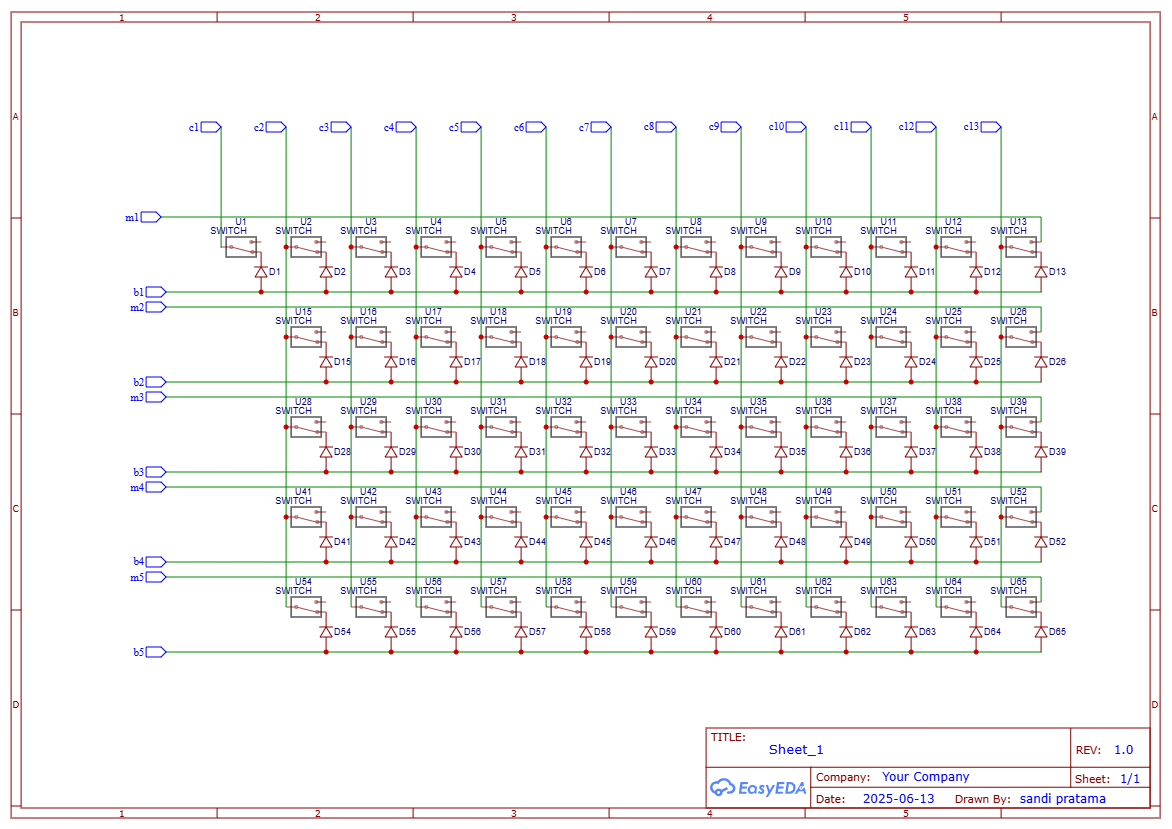
The GPIO pins of the microcontroller that are connected to the “k” lines of the key matrix are internally configured as inputs with pulldown resistors, whereas the GPIOs connected to the “u” and “d” lines are configured as outputs.
The scanning procedure is executed in a timer interrupt routine 1500 times per second. For each interrupt the following happens:
- loop over all “u” and “d” pins in the following matter “d1<=Hi, others<=Lo”, “u1<=Hi, others<=Lo”, “d2<=Hi, others<=Lo”, etc …
- capture the bit pattern of the twelve “k” pins
- loop over the bits in the captured pattern which correspond to individual key contacts and evaluate:
- if upper contact of key n is open, then increase (+1) the 16 bit integer in the array slice delay_mem[n] (acting as a counter for the delay time between upper contact opening/lower contact closing)
- if lower contact of key n is closed, then enqueue an entry to a ring buffer, consisting of the key number and delay_mem[n] (which is later to become a NOTE_ON MIDI event)
- if upper contact of key n is closed, then reset delay_mem[n] to zero and enqueue an entry to the ring buffer consisting of the key number and delay=0 (which is later to become a NOTE_OFF MIDI event)
In the normal execution thread (outside the interrupt), the entries from the ring buffer are dequeued and a MIDI message is generated and sent via the UART.
A MIDI message for a note on event of key #20 (example) and velocity 64 (example) consists of three bytes:
byte 1: 0×90 (shown as hex): “I announce you the beginning of a note on event on channel 0″
byte 2: 20 (shown as integer): “It’s about key #20″
byte 3: 64 (shown as integer): “The key was struck down with a velocity value of 64″ (possible values are 0-127)
These bytes have to be sent with 8N1 (standard) encoding and a data rate of 31250 baud.
Before sending the packet, the velocity has to be calculated from the key contact delay time. I assumed that, because velocity (speed) is a distance divided by the time to travel the distance, also the key velocity has to be proportional to 1/(key contact delay time). To adjust the velocity I introduced an arbitrary scaling factor c (which was set to 1440 by trial and error):
 I then check if the calculated value is greater than 127 (maximum allowed value). If it is greater I set it to constant 127.
When a ring buffer entry with delay==0 gets dequeued, the µC sends a NOTE_OFF MIDI message.
#include "keypins.h"
#include "stm32f10x.h"
#include "stm32f10x_rcc.h"
#include "stm32f10x_gpio.h"
#include "stm32f10x_usart.h"
#include "serial.h"

struct Buffer {
	u32 data[BUFFER_SIZE];
	uint8_t read;
	uint8_t write;
} buffer = { { }, 0, 0 };

uint8_t BufferIn(u32 byte) {
	uint8_t next = ((buffer.write + 1) & BUFFER_MASK);
	if (buffer.read == next)
		return FAIL;
	buffer.data[buffer.write] = byte;
	// buffer.data[buffer.write & BUFFER_MASK] = byte; // more secure
	buffer.write = next;
	return SUCCESS;
}

uint8_t BufferOut(u32 *pByte) {
	if (buffer.read == buffer.write)
		return FAIL;
	*pByte = buffer.data[buffer.read];
	buffer.read = (buffer.read + 1) & BUFFER_MASK;
	return SUCCESS;
}

void my_uitoa(uint32_t zahl, char* string) {
	int8_t i; // schleifenzähler

	string[8] = '\0'; // String Terminator
	for (i = 7; i >= 0; i--) {
		string[i] = (zahl % 10) + '0'; // Modulo rechnen, dann den ASCII-Code von '0' addieren
		zahl /= 10;
	}
}

void Delay(unsigned int volatile nCount) {

	for (; nCount != 0; nCount--)
		;

}

void binstr(char* s, u16 word) {
	u8 i;
	for (i = 0; i < 16; i++) {
		if (word & (1 << i)) {
			s[15 - i] = '1';
		} else {
			s[15 - i] = '0';
		}
	}

	s[16] = '\0';
}

void keypins_init(void) {

	GPIO_InitTypeDef GPIO_InitStructure;

	RCC_APB2PeriphClockCmd(RCC_APB2Periph_GPIOA, ENABLE);
	RCC_APB2PeriphClockCmd(RCC_APB2Periph_GPIOB, ENABLE);
	RCC_APB2PeriphClockCmd(RCC_APB2Periph_GPIOC, ENABLE);
//	RCC_APB2PeriphClockCmd(RCC_APB2Periph_GPIOD, ENABLE);
//	RCC_APB2PeriphClockCmd(RCC_APB2Periph_GPIOE, ENABLE);

	// u/d rails side push pull, initialize with zero!
	GPIO_InitStructure.GPIO_Mode = GPIO_Mode_Out_PP;
	GPIO_InitStructure.GPIO_Speed = GPIO_Speed_50MHz;

	GPIO_InitStructure.GPIO_Pin = U1;
	GPIO_Init(U1_PORT, &GPIO_InitStructure);
	GPIO_WriteBit(U1_PORT, U1, Bit_RESET);
	GPIO_InitStructure.GPIO_Pin = U2;
	GPIO_Init(U2_PORT, &GPIO_InitStructure);
	GPIO_WriteBit(U2_PORT, U2, Bit_RESET);
	GPIO_InitStructure.GPIO_Pin = U3;
	GPIO_Init(U3_PORT, &GPIO_InitStructure);
	GPIO_WriteBit(U3_PORT, U3, Bit_RESET);
	GPIO_InitStructure.GPIO_Pin = U4;
	GPIO_Init(U4_PORT, &GPIO_InitStructure);
	GPIO_WriteBit(U4_PORT, U4, Bit_RESET);
	GPIO_InitStructure.GPIO_Pin = U5;
	GPIO_Init(U5_PORT, &GPIO_InitStructure);
	GPIO_WriteBit(U5_PORT, U5, Bit_RESET);
	GPIO_InitStructure.GPIO_Pin = U6;
	GPIO_Init(U6_PORT, &GPIO_InitStructure);
	GPIO_WriteBit(U6_PORT, U6, Bit_RESET);
	GPIO_InitStructure.GPIO_Pin = U7;
	GPIO_Init(U7_PORT, &GPIO_InitStructure);
	GPIO_WriteBit(U7_PORT, U7, Bit_RESET);

	GPIO_InitStructure.GPIO_Pin = D1;
	GPIO_Init(D1_PORT, &GPIO_InitStructure);
	GPIO_WriteBit(D1_PORT, D1, Bit_RESET);
	GPIO_InitStructure.GPIO_Pin = D2;
	GPIO_Init(D2_PORT, &GPIO_InitStructure);
	GPIO_WriteBit(D2_PORT, D2, Bit_RESET);
	GPIO_InitStructure.GPIO_Pin = D3;
	GPIO_Init(D3_PORT, &GPIO_InitStructure);
	GPIO_WriteBit(D3_PORT, D3, Bit_RESET);
	GPIO_InitStructure.GPIO_Pin = D4;
	GPIO_Init(D4_PORT, &GPIO_InitStructure);
	GPIO_WriteBit(D4_PORT, D4, Bit_RESET);
	GPIO_InitStructure.GPIO_Pin = D5;
	GPIO_Init(D5_PORT, &GPIO_InitStructure);
	GPIO_WriteBit(D5_PORT, D5, Bit_RESET);
	GPIO_InitStructure.GPIO_Pin = D6;
	GPIO_Init(D6_PORT, &GPIO_InitStructure);
	GPIO_WriteBit(D6_PORT, D6, Bit_RESET);
	GPIO_InitStructure.GPIO_Pin = D7;
	GPIO_Init(D7_PORT, &GPIO_InitStructure);
	GPIO_WriteBit(D7_PORT, D7, Bit_RESET);

	// key pins are input with pulldown!
	GPIO_InitStructure.GPIO_Mode = GPIO_Mode_IPD;

	GPIO_InitStructure.GPIO_Pin = KEY01;
	GPIO_Init(KEY01_PORT, &GPIO_InitStructure);
	GPIO_InitStructure.GPIO_Pin = KEY02;
	GPIO_Init(KEY02_PORT, &GPIO_InitStructure);
	GPIO_InitStructure.GPIO_Pin = KEY03;
	GPIO_Init(KEY03_PORT, &GPIO_InitStructure);
	GPIO_InitStructure.GPIO_Pin = KEY04;
	GPIO_Init(KEY04_PORT, &GPIO_InitStructure);
	GPIO_InitStructure.GPIO_Pin = KEY05;
	GPIO_Init(KEY05_PORT, &GPIO_InitStructure);
	GPIO_InitStructure.GPIO_Pin = KEY06;
	GPIO_Init(KEY06_PORT, &GPIO_InitStructure);
	GPIO_InitStructure.GPIO_Pin = KEY07;
	GPIO_Init(KEY07_PORT, &GPIO_InitStructure);
	GPIO_InitStructure.GPIO_Pin = KEY08;
	GPIO_Init(KEY08_PORT, &GPIO_InitStructure);
	GPIO_InitStructure.GPIO_Pin = KEY09;
	GPIO_Init(KEY09_PORT, &GPIO_InitStructure);
	GPIO_InitStructure.GPIO_Pin = KEY10;
	GPIO_Init(KEY10_PORT, &GPIO_InitStructure);
	GPIO_InitStructure.GPIO_Pin = KEY11;
	GPIO_Init(KEY11_PORT, &GPIO_InitStructure);
	GPIO_InitStructure.GPIO_Pin = KEY12;
	GPIO_Init(KEY12_PORT, &GPIO_InitStructure);

	// sustain pin is pullup
	GPIO_InitStructure.GPIO_Mode = GPIO_Mode_IPU;
	GPIO_InitStructure.GPIO_Pin = SUST;
	GPIO_Init(SUST_PORT, &GPIO_InitStructure);
}

void keypins_set_u(u16 word_in) {
	// set the u pins to a defined bit pattern
	u32 word = (u32) word_in;

	U1_PORT ->BSRR = (U1 << 16) | (((word & (1 << 0)) >> 0) * U1 );
	U2_PORT ->BSRR = (U2 << 16) | (((word & (1 << 1)) >> 1) * U2 );
	U3_PORT ->BSRR = (U3 << 16) | (((word & (1 << 2)) >> 2) * U3 );
	U4_PORT ->BSRR = (U4 << 16) | (((word & (1 << 3)) >> 3) * U4 );
	U5_PORT ->BSRR = (U5 << 16) | (((word & (1 << 4)) >> 4) * U5 );
	U6_PORT ->BSRR = (U6 << 16) | (((word & (1 << 5)) >> 5) * U6 );
	U7_PORT ->BSRR = (U7 << 16) | (((word & (1 << 6)) >> 6) * U7 );

}

void keypins_set_d(u16 word_in) {
	// set the d pins to a defined bit pattern
	u32 word = (u32) word_in;

	D1_PORT ->BSRR = (D1 << 16) | (((word & (1 << 0)) >> 0) * D1 );
	D2_PORT ->BSRR = (D2 << 16) | (((word & (1 << 1)) >> 1) * D2 );
	D3_PORT ->BSRR = (D3 << 16) | (((word & (1 << 2)) >> 2) * D3 );
	D4_PORT ->BSRR = (D4 << 16) | (((word & (1 << 3)) >> 3) * D4 );
	D5_PORT ->BSRR = (D5 << 16) | (((word & (1 << 4)) >> 4) * D5 );
	D6_PORT ->BSRR = (D6 << 16) | (((word & (1 << 5)) >> 5) * D6 );
	D7_PORT ->BSRR = (D7 << 16) | (((word & (1 << 6)) >> 6) * D7 );

}

u16 keypins_read_keys(void) {
        // read out all k pins
	u16 return_val = 0;

	return_val |= GPIO_ReadInputDataBit(KEY01_PORT, KEY01 ) << 0;
	return_val |= GPIO_ReadInputDataBit(KEY02_PORT, KEY02 ) << 1;
	return_val |= GPIO_ReadInputDataBit(KEY03_PORT, KEY03 ) << 2;
	return_val |= GPIO_ReadInputDataBit(KEY04_PORT, KEY04 ) << 3;
	return_val |= GPIO_ReadInputDataBit(KEY05_PORT, KEY05 ) << 4;
	return_val |= GPIO_ReadInputDataBit(KEY06_PORT, KEY06 ) << 5;
	return_val |= GPIO_ReadInputDataBit(KEY07_PORT, KEY07 ) << 6;
	return_val |= GPIO_ReadInputDataBit(KEY08_PORT, KEY08 ) << 7;
	return_val |= GPIO_ReadInputDataBit(KEY09_PORT, KEY09 ) << 8;
	return_val |= GPIO_ReadInputDataBit(KEY10_PORT, KEY10 ) << 9;
	return_val |= GPIO_ReadInputDataBit(KEY11_PORT, KEY11 ) << 10;
	return_val |= GPIO_ReadInputDataBit(KEY12_PORT, KEY12 ) << 11;

	return return_val;

}

void keypins_scan(void) {
	static u16 delay_mem[84] = { 0, 0, 0, 0, 0, 0, 0, 0, 0, 0, 0, 0, 0, 0, 0, 0,
			0, 0, 0, 0, 0, 0, 0, 0, 0, 0, 0, 0, 0, 0, 0, 0, 0, 0, 0, 0, 0, 0, 0,
			0, 0, 0, 0, 0, 0, 0, 0, 0, 0, 0, 0, 0, 0, 0, 0, 0, 0, 0, 0, 0, 0, 0,
			0, 0, 0, 0, 0, 0, 0, 0, 0, 0, 0, 0, 0, 0, 0, 0, 0, 0, 0, 0, 0, 0 };
	static u16 cur_row;
	static u8 i;
	uint16_t border_mask;
	static u8 j;
	static u8 key_number, note_number;

	for (i = 0; i < 14; i++) { // loop through the octaves: 7 octaves with one d and one u line = 14 iterations

		// set one line low each and read out the keypins
		// distinguish between d and u output pins:
		if (i % 2) { // is uneven row = upper contact
			keypins_set_d(0); // set down pins to 0
			keypins_set_u((1 << (i / 2))); // seit u pin #i high
			Delay(30);
			if (i / 2 == 0) {
				border_mask = 0b111111111000; // mask out open keys at the lower border of the keyboard
			} else if (i / 2 == 6) {
				border_mask = 0b000001111111; // mask out open keys at the upper border of the keyboard
			} else {
				border_mask = 0b111111111111; // mask unused part of the 16bit variable, there are only 12 keypins
			}
			cur_row = border_mask & (~keypins_read_keys()); // here the result of keypins_read_keys() gets inverted
			// to account for the fact that the upper key contacts are closed in idle state
			//
			// If your keyboard has the upper contacts open in idle state, then delete line 229 and uncomment
			// the following line:
			// cur_row = border_mask & (keypins_read_keys());

		} else { // is even row = lower contact
			keypins_set_u(0); // set up pins to 0
			keypins_set_d((1 << (i / 2))); // set d pin #i high
			Delay(30);
			cur_row = (keypins_read_keys());
		}

		for (j = 0; j < 12; j++) { // loop through the 12 keys per octave

			key_number = (i / 2) * 12 + j;
			note_number = key_number + BOTTOM_KEY;

			if (i % 2) { // is uneven row = upper contact

				if (cur_row & (1 << j)) { // upper contact closed
					if (delay_mem[key_number] < 65534) { // count time that key is on, stop at 65534 (0xFFFE)
						delay_mem[key_number]++;
					}
				} else { // upper contact open -> reset to idle state
					if (delay_mem[key_number] == 65535) { // this number means that a NOTE ON event has been sent
						// and a NOTE OFF is due

						BufferIn((u32) note_number); // note number, but delay == 0 => send a NOTE OFF event

					}
					delay_mem[key_number] = 0;
				}

			} else { // is even row = lower contact

				if (cur_row & (1 << j)) { // lower contact closed
					if (delay_mem[key_number] < 65535) {

						BufferIn(
								((u32) note_number)
										| (((u32) delay_mem[key_number]) << 16));

						delay_mem[key_number] = 65535; // this delay count cannot be reached
						// by waiting, it is used as an indicator that a NOTE ON event has been sent
						// and a NOTE OFF event still has to be sent as soon as the upper contact
						// returns to idle state
					}

				} else { //lower contact open

				}
			}
		}
	}
}


void sust_scan(void){
   // read out the the sustain pedal, put sustain events in the Buffer

	static u8 old_sust_state, sust_state = 0;

	sust_state = GPIO_ReadInputDataBit(SUST_PORT, SUST );
	if(sust_state && (!(old_sust_state)) ) {//detect rising edge on sustain pedal
		BufferIn(SUSTAIN_ON);
	}
	if((!(sust_state)) && old_sust_state ) {//detect falling edge on sustain pedal
		BufferIn(SUSTAIN_OFF);
	}

	old_sust_state = sust_state;

}

void velotask(void) {
  // unqueue events from the buffer and convert them to MIDI data
  // send the MIDI data via UART
	u32 payload;
	int16_t velo;

	while (1) {

		if (BufferOut(&payload)) {

			if (payload & 0xFFFF0000) { //it's a note on event, because there is velocity information


			        // calculate the velocity from the delay time
			        // velocity ~ 1/delay
				velo = 1400 / (payload >> 16); // upper 16 bits of payload are delay time
				if (velo < 0) {
					velo = 0;
				} else if (velo > 127) {
					velo = 127;
				}

				comm_put(0x90); //Note ON
				comm_put((u8) payload); //Note
				comm_put(velo); //Velocity 0-127
			} else if (((u8) payload) < BOTTOM_KEY) { // control?
				if (payload == SUSTAIN_ON){
					comm_put(0b10110000); //Control Change
					comm_put(64); //Sustain/Damper Pedal
					comm_put(0); //on
				}
				if (payload == SUSTAIN_OFF){
					comm_put(0b10110000); //Control Change
					comm_put(64); //Sustain/Damper Pedal
					comm_put(127); //off
				}

			} else { // it's a note off event
				comm_put(0x80); //Note OFF
				comm_put((u8) payload); //Note
				comm_put(0x00); //Velocity: 0
			}

		}

	}

}