I am looking for advice for how to poll 57 linear Hall effect sensors (49E) so that I can use the reading to calculate MIDI velocity for 57 buttons. I have previous experience with building custom computer keyboards and have handwired many keyboard matrices as well as made simple PCBs. Would the same work for Hall effect sensors? The idea would be to have 6 rows of 10 sensors with the sensor OUT leg connected to the row via a diode to prevent ghosting. Then there would be 10 columns with an Arduino digital pin OUT connected to the sensor VCC leg. The ground legs to ground of course. I would pull one Arduino digital pin high at the time and read each rows sensor value to get the values of all 57 sensors in one read cycle. Just as a normal keyboard matrix. I would need 6 analog inputs and 10 digital outputs which is no issue. I think it should be possible to do fast enough to get good velocity data.
I have a few questions I don't know the answer too though since I am not fluent in electronics. Will a HIGH digital pin suffice as VCC for the sensors? Do the Hall effect sensor need time to settle after "being activated" before I can take a reading? Will the diode mess with the "analog signal" from the sensor out leg? Do you foresee any other issues with this approach?
Sounds strange. A swich goes from off to on, or from on to off. Bouncing is a fact in the time dimension but it's varying for each individual..
What do You think of being "speed"?
I used the word switch cordially. I meant to say button. The velocity will of course be calculated based on the time elapsed between two threshold values read from the linear Hall sensor and scaled to between 0 and 127. The button move a magnet in the z-axis above the sensor.
You know, that if you made a test set with one Hall sensor and one push button, you could program various scenarios and find the answers your self. First would be to find out how to know that button was pushed, the second to discover how many time you need to read the Hall sensor output in order to compute a velocity number.
Have you researched how MIDI keyboards are normally made and how they sense velocity?
I'd have a few concerns -
The hall sensors will have tolerances/variations and they may have to be individually calibrated. But that may be true for any analog sensor that you adapt for this application.
With magnetics, you'll get the inverse square effect and the results my not be useful.
With analog, matrix wiring may not be practical or possible. Multiplexing might work better. The chip used in the Arduino Uno has one internal analog-to-digital converter multiplexed to multiple analog-input pins. Of course, with a shared ADC, reading speed could be an issue. Musical notes are "slow" compared to a microprocessor but the "attack" goes-by quickly and that could be an issue.
I do have experience with electronics but I don't know much about keyboards/synths. I doubt I could build a keyboard as cheaply as I could buy one, especially if I wanted velocity sensing. (And personally, I don't have the mechanical-construction skills to make a "nice" keyboard.)
P.S.
I'd recommend that you start-out "prototyping" with a smaller keyboard... Maybe one octave, and see how it goes. And just one key before that so you can test velocity, etc.
Most commonly they use the stacked switches approach. With that solution I would ned 114 switches in a matrix instead. Nothing inherently difficult with that approach but being a computer keyboard aficionado I find myself not liking the feel of the buttons.
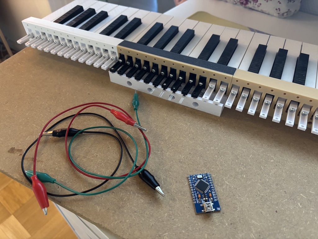
I have made a prototype to try out the sensor/magnet approach and I find that it works for detecting key presses. I have not wired up all the switches though hence my questions about an analog matrix in my OP and enabling the sensor with a digital pin. I have a few analog 16 channel multiplexers if needed but am currently more attracted to the matrix solution.
I have however decided to leave the piano key approach for this project and use LEKKER switches (from Wooting) instead and build a Wiki-Hayden layout but only with 57 keys (3 octaves in this layout) since I currently only have that many sensors.
I'll commit to the experiment and buy a set of LEKKER switches and find out.
As far as i know one of the keyboards i have, uses 2 switches, and the 1 switch is make to Vcc and starts charging a small capacitor (through a resistor) until the 2nd switch is pressed, which stops the charging and initiates the analog reading of the charge of the capacitor.
Measuring time using a MCU, for that many keys, i think is not going to be reliable enough. Of course that does depend on the processing speed.
The Vax 77 keyboard used hall effect sensors as you describe and it was the most wonderful action - a true joy to play... I did require individual adjustment of the keys though!