We are doing our final year project in highschool which is a venduino: a vending machine made with an arduino.
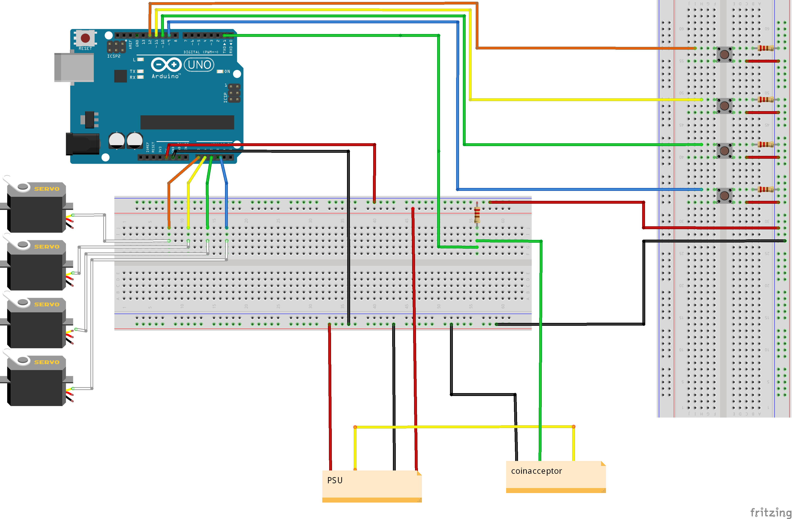
The arduino is connected to 4 push buttons, 4 continuous servo motors and a coin acceptor. The currency put in the coin acceptor is saved and when the user has enough currency they can press a button to make a servo motor rotate.
We have managed to make the components function before, but when we attached our components to the "Venduino" casing we stumbled upon a problem.
The buttons that worked perfectly before have started acting like they are pressed, when they are not.
When troubleshooting we discovered that this happened even when the buttons were not in any way connected to the arduino. Meaning that the digital pins 9-12 (our button pins) on the arduino were empty.
The project is due tomorrow and we would very much appreciate any help given! ![]()
(Sorry if you lose a few braincells while reading our code, we're new to this.)
  #include <Servo.h>

  #include <EEPROM.h>

  // myntacceptorn
  // variable use to measuer the intervals inbetween impulses
  int i=0;
  // Number of impulses detected
  int impulsCount=0;
  // Sum of all the coins inseted
  int total_amount=0;


  //constants
  const int btnPin1 = 12;
  const int btnPin2 = 11;
  const int btnPin3 = 10;
  const int btnPin4 = 9;

  //Button button1(btnPin1);


  const int servoPin1 = A0;
  const int servoPin2 = A1;
  const int servoPin3 = A2;
  const int servoPin4 = A3;

  Servo servo1;
  Servo servo2;
  Servo servo3;
  Servo servo4;

  int servoDelay = 5000;


void setup() {
  // put your setup code here, to run once:
  Serial.begin(9600);


  // initialize the pushbutton pin as an input:
  pinMode(btnPin1, INPUT);
  pinMode(btnPin2, INPUT);
  pinMode(btnPin3, INPUT);
  pinMode(btnPin4, INPUT);


  // Interrupt connected to PIN D2 executing IncomingImpuls function when signal goes from HIGH to LOW
 attachInterrupt(0,incomingImpuls, FALLING);
 EEPROM.get(0, total_amount);

}

void incomingImpuls()
{
  impulsCount=impulsCount+1;
  i=0;
}

void loop() {
  // put your main code here, to run repeatedly:
  i=i+1;

  Serial.print("i=");
  Serial.print(i);
  Serial.print(" Impulses:");
  Serial.print(impulsCount);
  Serial.print(" Total:");
  Serial.println(total_amount);


  if (impulsCount > 4){
    impulsCount=4;
    i = 0;
  }
  if (i>=30 and impulsCount==1){
    total_amount=total_amount+1;
    impulsCount=0;
    EEPROM.put(0, total_amount);
  }
   if (i>=30 and impulsCount==2){
    total_amount=total_amount+2;
    impulsCount=0;
    EEPROM.put(0, total_amount);
  }
   if (i>=30 and impulsCount==3){
    total_amount=total_amount+5;
    impulsCount=0;
    EEPROM.put(0, total_amount);
  }
   if (i>=30 and impulsCount==4){
    total_amount=total_amount+10;
    impulsCount=0;
    EEPROM.put(0, total_amount);
  }
   if (i>=500){
    impulsCount=0;
    i = 0;
  }


  CheckBtn();
}


// Control if a button is pressed
void CheckBtn() {
    // read the state of the pushbutton value:
    int btnstate1 = 0;
    int btnstate2 = 0;
    int btnstate3 = 0;
    int btnstate4 = 0;

    btnstate1 = digitalRead(btnPin1);
    btnstate2 = digitalRead(btnPin2);
    btnstate3 = digitalRead(btnPin3);
    btnstate4 = digitalRead(btnPin4);

    if (btnstate1 == HIGH && btnstate2 == LOW && btnstate3 == LOW && btnstate4 == LOW && total_amount >= 1){
      Servo1();
      total_amount -= 1;
    }
    if (btnstate2 == HIGH && btnstate1 == LOW && btnstate3 == LOW && btnstate4 == LOW && total_amount >= 2){
      Servo2();
      total_amount -= 2;
    }
   if (btnstate3 == HIGH && btnstate2 == LOW && btnstate1 == LOW && btnstate4 == LOW && total_amount >= 5){
      Servo3();
      total_amount -= 5;
    }
    if (btnstate4 == HIGH && btnstate2 == LOW && btnstate3 == LOW && btnstate1 == LOW && total_amount >= 10){
      Servo4();
      total_amount = 0;
    }
}

// Activate Servo 1
void Servo1(){
  Serial.write("red");
  Serial.println();

  for(int i=0; i<57; i++){                  // change this to adjust +- full revolution
    digitalWrite(servoPin1,HIGH);
    delayMicroseconds(1700);
    digitalWrite(servoPin1,LOW);
    delay(18.5); // 18.5ms
   }

}

// Activate Servo 2
void Servo2(){
  Serial.write("blue");
  Serial.println();

  for(int i=0; i<57; i++){                  // change this to adjust +- full revolution
    digitalWrite(servoPin2,HIGH);
    delayMicroseconds(1700);
    digitalWrite(servoPin2,LOW);
    delay(18.5); // 18.5ms
   }
}

// Activate Servo 3
void Servo3(){
  Serial.write("green");
  Serial.println();

  for(int i=0; i<57; i++){                  // change this to adjust +- full revolution
    digitalWrite(servoPin3,HIGH);
    delayMicroseconds(1000);
    digitalWrite(servoPin3,LOW);
    delay(18.5); // 18.5ms
   }
}

// Activate Servo 4
void Servo4(){
  Serial.write("yellow");
  Serial.println();

  for(int i=0; i<57; i++){                  // change this to adjust +- full revolution
    digitalWrite(servoPin4,HIGH);
    delayMicroseconds(1000);
    digitalWrite(servoPin4,LOW);
    delay(18.5); // 18.5ms
   }
}