Void loop not looping with cycles

Its a four directional traffic light system that turns on based on a pattern. I just started and everything was going well but in void loop, only cycleOne is looping, not cycleTwo. This is for my 10th grade summative so I just need clarity on what needs to be changed.

int thispin;
int lopin=2;
int hipin=13;
int n;
int e;

void setup()
{
for (thispin=lopin; thispin<=hipin; thispin++)
{pinMode (thispin, OUTPUT);
}}

void cycleOne()
{
int hipin=10;
for (int n=hipin; n>=hipin; n+0)
{ digitalWrite (n, HIGH);
delay (1000);
digitalWrite (n, LOW);
}}

void cycleTwo()
{
int hipin=12;
for (int e=hipin; e>=hipin; e+0)
{ digitalWrite (e, HIGH);
delay (1000);
}}

void loop()
{
cycleOne();
cycleTwo();
}

Welcome to the forum

Please follow the advice given in the link below when posting code, in particular the section entitled 'Posting code and common code problems'

Use code tags (the < CODE/ > icon above the compose window) to make it easier to read and copy for examination

https://forum.arduino.cc/t/how-to-get-the-best-out-of-this-forum

What exactly are you hoping that this statement will accomplish? I'm honestly mystified.

for (int n=hipin; n>=hipin; n+0)

What will be the series of values of n produced by this for loop ?

Try printing it inside the for loop then read up on for loops

Not being used here but the divider is not being powered.

I forgot digitalWrite existed :skull:

oh thanks, I didn't see that

I imagine that's an answer to some question, but not the one I asked. Which was

Its supposed to set the pin to high and if the pin was less than or equal to the hipin, the pin would remain the same... and I would do that for the rest of my code

There are no mentions of any pins in that for statement.

I did not ask what you expected the loop following the for statement to do.

I am still asking what you expect the for statement to do. Look at it. Look at it again. It makes no sense.

An infinite loop never exits.

I see that now

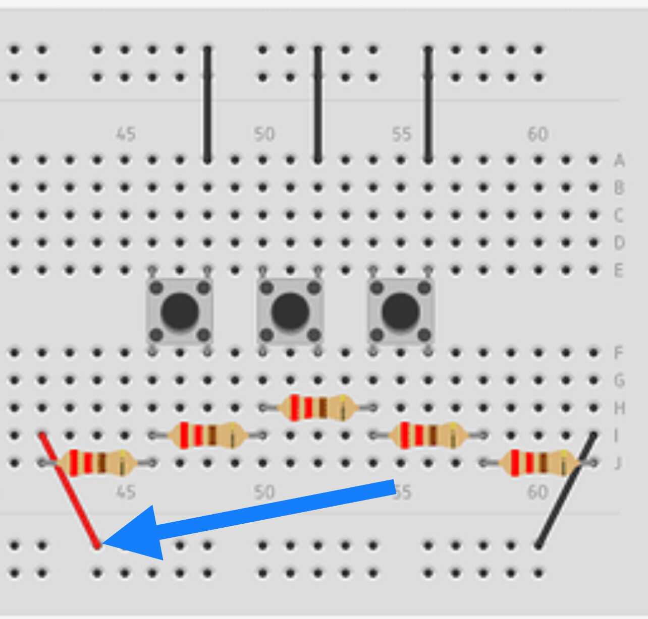
Hello, I am working on a four directional traffic light system. The problem I am struggling to fix is the 1st push button (Maintenance button). It is supposed to turn all LEDS in each direction red, than green for an interval of 1.5 seconds. I pushed the button at simulation time 00:14:00 (14 seconds) and it started going red and green at a delayed 20 seconds which should not be happening. Also, sometimes during the red and green phase, it turns yellow... I don't know why this is. After I let go of the button, the lights keep flickering red and green for a little while and don't resume to their regular pattern.

Traffic light system <------ LINK TO VIDEO

Code:

int thispin;
int lopin=2;
int hipin=13;
int elo=2;
int emed=3;
int ehi=4;
int slo=5;
int smed=6;
int shi=7;
int nlo=8;
int nmed=9;
int nhi=10;
int wlo=11;
int wmed=12;
int whi=13;
int voltageValue;

void setup()
{
for (thispin=lopin; thispin<=hipin; thispin++)
{pinMode (thispin, OUTPUT);
 Serial.begin (1000);
}}

void cycleOne()
{
digitalWrite (nhi, HIGH);
digitalWrite (shi, HIGH);
digitalWrite (elo, HIGH);
digitalWrite (wlo, HIGH);
delay (4000);
digitalWrite (elo, LOW);
digitalWrite (wlo, LOW);
}

  
  void cycleTwo()
{
digitalWrite (emed, HIGH);
digitalWrite (wmed, HIGH);
delay (1000);
digitalWrite (emed, LOW);
digitalWrite (wmed, LOW);
}

void cycleThree()
{
digitalWrite (ehi, HIGH);
digitalWrite (whi, HIGH);
delay (1000);
}

void cycleFour()
{
digitalWrite (nhi, LOW);
digitalWrite (shi, LOW);
digitalWrite (nlo, HIGH);
digitalWrite (slo, HIGH);
delay (4000);
digitalWrite (nlo, LOW);
digitalWrite (slo, LOW);
}

void cycleFive()
{
digitalWrite (nmed, HIGH);
digitalWrite (smed, HIGH);
delay (1000);
digitalWrite (nmed, LOW);
digitalWrite (smed, LOW);
}

void cycleSix()
{
digitalWrite (nhi, HIGH);
digitalWrite (shi, HIGH);
delay (1000);
digitalWrite (ehi, LOW);
digitalWrite (whi, LOW);
}

void cycleMaintenance()
{
if (voltageValue==804) {
digitalWrite (nlo, LOW);
digitalWrite (slo, LOW);
digitalWrite (elo, LOW);
digitalWrite (wlo, LOW); 
digitalWrite (nmed, LOW);
digitalWrite (smed, LOW);
digitalWrite (emed, LOW);
digitalWrite (wmed, LOW); 
digitalWrite (nhi, HIGH);
digitalWrite (shi, HIGH);
digitalWrite (ehi, HIGH);
digitalWrite (whi, HIGH);
delay (1500);
digitalWrite (nhi, LOW);
digitalWrite (shi, LOW);
digitalWrite (ehi, LOW);
digitalWrite (whi, LOW);
digitalWrite (nlo, HIGH);
digitalWrite (slo, HIGH);
digitalWrite (elo, HIGH);
digitalWrite (wlo, HIGH);
delay (1500);}
}

  
  void loop()
{
voltageValue = analogRead(A5);
cycleOne();
cycleMaintenance();
cycleTwo();
cycleMaintenance();
cycleThree();
cycleMaintenance();
cycleFour();
cycleMaintenance();
cycleFive();
 cycleMaintenance();
cycleSix();
cycleMaintenance();
}

For my summative

image
I have a cycle maintenance in between each cycle so why would the button not work

Is there a substitute for the delay command?

This appears to be the same code and same problems that were brought up in Void loop not looping with cycles . The crosspost has been reported.

Hello

Decode these variable names to generally understandable names .

int lopin=2;
int hipin=13;
int elo=2;
int emed=3;
int ehi=4;
int slo=5;
int smed=6;
int shi=7;
int nlo=8;
int nmed=9;
int nhi=10;
int wlo=11;
int wmed=12;
int whi=13;
int lopin=2; - lowest output (2)
int hipin=13; highest output (13)
int thispin; - current output
int elo=2; - east side green led
int emed=3; east side yellow led
int ehi=4; east side red led 
int slo=5; south green led
int smed=6; south yellow led
int shi=7; south red led
int nlo=8; north green led... and so on
int nmed=9;
int nhi=10;
int wlo=11;
int wmed=12;
int whi=13;

lo are green leds
med are yellow leds
hi are red leds

N,E,S,W are directions