I made this h-bridge circuit out of 2 pnp transistors tip32 and 2 npn transistors tip31
4 protection diodes
Load is a 2.5 ohm coil
Power 8v
Problem is that there is a voltage drop of about 3v across the h-bridge, how can I eliminate this voltage drop?
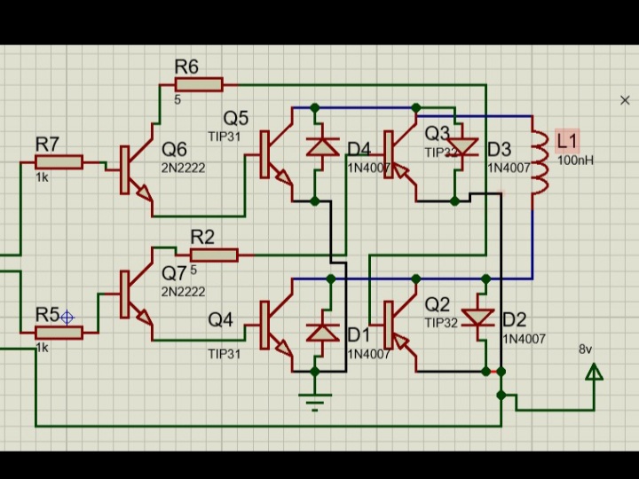
In your diagram there is no indication where any positive supply voltage is fed in. As shown the PNP transistors never can be turned ON.

Your circuit will turn on and kill both transistors of one side at once. The OP circuit does this aspect right, but has other things wrong.
Sorry, I posted the wrong link. Fixed.
Now your circuit is controlled by signals close to Vcc if the driver PNP transistors shall be turned OFF. For nowadays applications with negative GND the driver transistors should be NPN.
This is due to the Darlington transistors which can drop up to 4V (2V each). Nowadays H-bridges use MOSFETs with very low voltage drops, at the cost of special driver circuits.
Now your circuit is controlled by signals close to Vcc if the driver PNP transistors shall be turned OFF.
Correct. The circuit was posted merely to illustrate the layout. As stated in my post.
It is not intended to correct the OP's design.