In the context of using an old hard disk motor (or similar) as a tacho/encoder, what sort of peak voltage would you typically see when turning it just with your fingers?
Are these usable for a jog wheel type application or is there effectively are large dead zone at the low end of the speed scale making it impractical unless you add an amplifier or comparator?
Currently I don't have any hardware to test and this sort of application doesn't appear in motor datasheets.
Well, that sort of depends on the old hard disk motor, don't you think? I remember old hard disk motors that were three phase 208 volts AC. I remember other old hard disk motors that were 120 VAC, 60 Hz. I remember other old hard disk motors that were very tiny and powered by pulsing DC.
This was a Hitachi, I think, hard drive that was going to be attached to a Data General mini-computer and going to a bank for their accounting purposes. To run off the banks 220 VAC we also had to include a phase converter, another big box. Both went into a U-Haul trailer to deliver to the bank. The computer was already there.
DC motor speed is characterised by its "kV" rating which is typically the voltage per 1000 rpm. Basically the motors will run unloaded at a speed where the back emf they generate equals the supply voltage. A bit of Googling suggests that HDD motors run at 7200 rpm, and their drivers presumably work from 5v, so the kV rating would be 7200/5 = 1440. In other words, if you feed them with 1V they should spin at 1440 rpm = 120 rpm = 2 revs/sec. That sounds to me eminently detectable with an Arduino analogue input, a great idea. They also have a 3-phase output so you can sense direction and even interpolate for better resolution.
Some years back a small US company made a control board that could take the pulses generated by a stepper motor driven round and used them to make an encoder for CNC manual pulse generators. I have a stepper on my desk and a scope nearby, I'll give it a whirl. Sadly I don't have an old HDD motor for comparison.
I don't know what I did there! On 1v they would spin at 1440rpm = 24 RPS. So if you spun them at 1 RPS you should get 40mv about, so detectable with a bit of op amp gain.
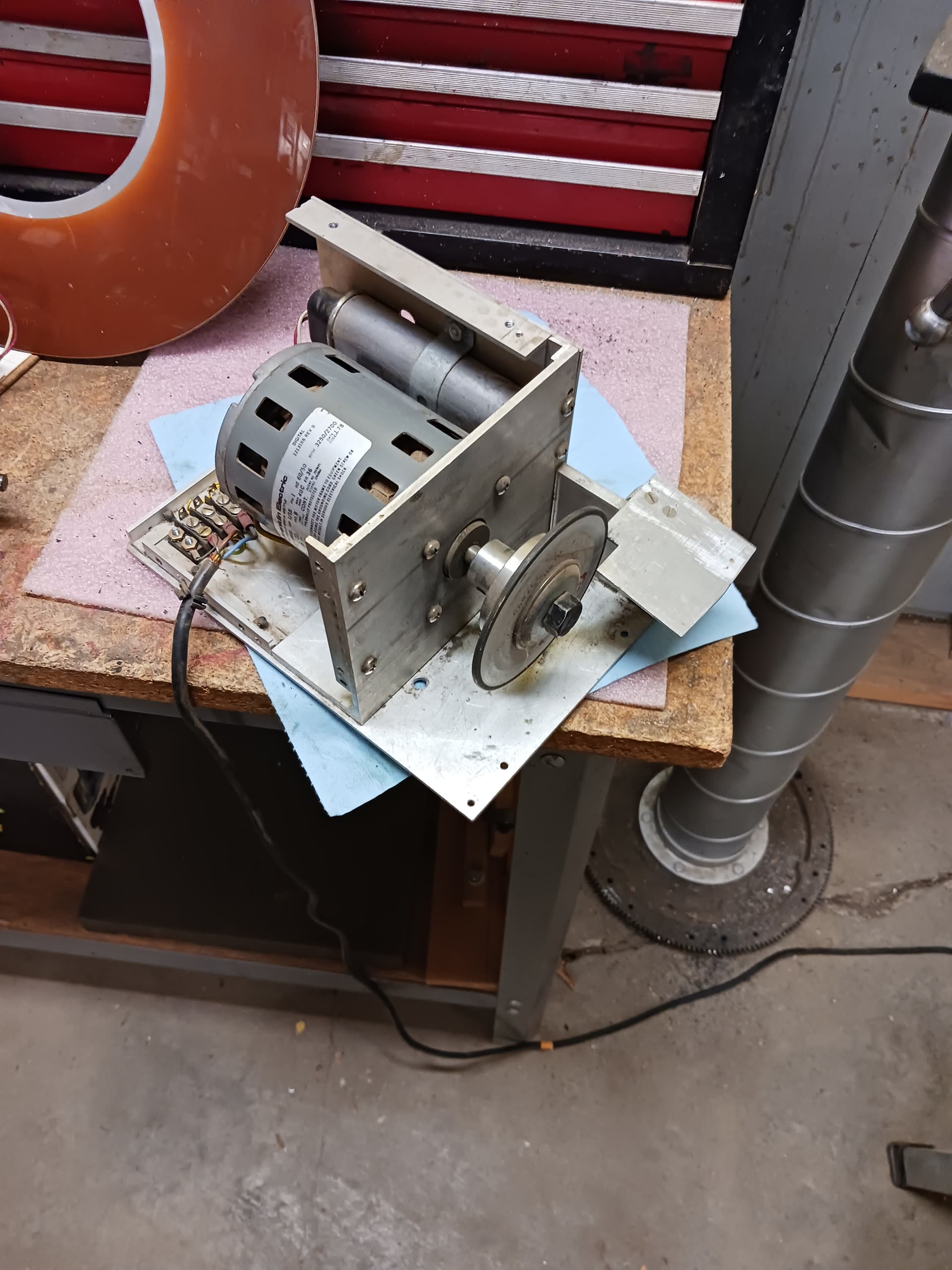
I have three hard disk drive motors, so I went out to the shop to get pictures. One motor is powering a carbide tooling sharpener. The other two are still waiting for a project.
The motors came from a DEC PDP? minicomputer which must have had three drives. The 10MB drives were made by Control Data, CDC, in Colorado. They made 10s of thousands of them. Every minicomputer had at least one.
The platter is from one of the drives. 5MB on each side. It is 14 inches in diameter. The platter assembly was belt driven from one of the motors.
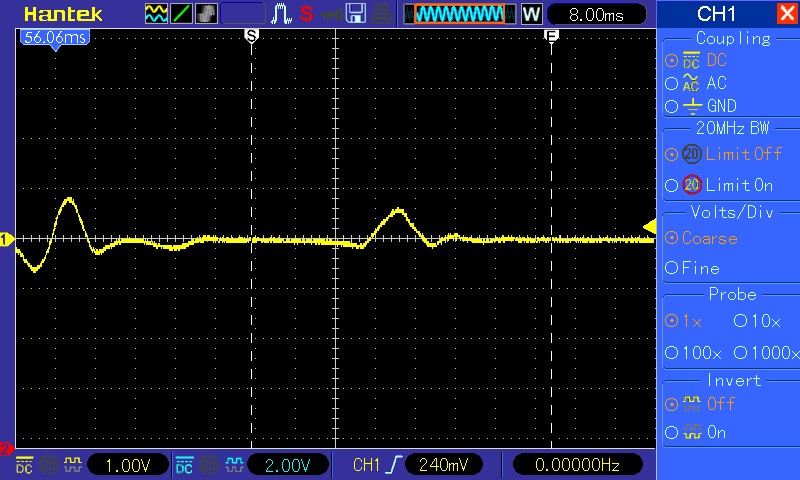
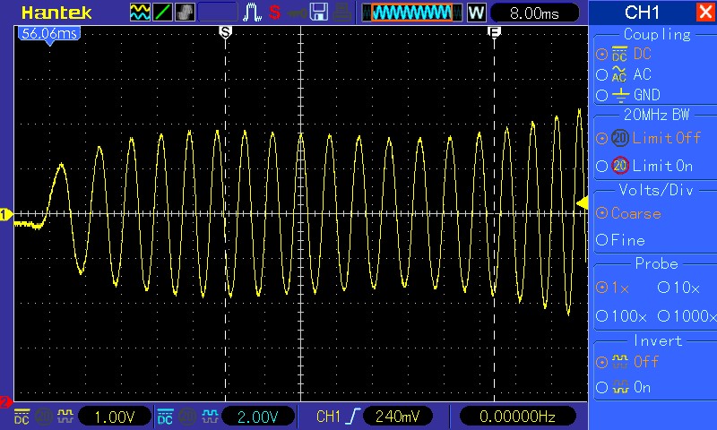
Going back to the original question, I don't have a BLDC motor to test but I just now I connected a scope probe to a NEMA17 400 step/rev motor that was sitting on my desk and recorded some waveforms while twiddling the shaft with my fingers.
The three pics are at different speeds, the middle one being much the slowest. Looks like there's lots of volts to play with but the waveform changes from isolated pulses at low speed to essentially sinusoidal at high. Might be a challenge to decode and one might get a dead zone for very slow twiddles.
Completely addressable with gears, or shafts. A shaft on motor and a shaft on knob, if knob shaft is twice the size as motor shaft then motor will turn twice as fast as knob is turned. Same for gears, if tooth count of gear on knob is twice tooth count of gear on motor, motor will turn twice as fast as knob.
Indeed (though I assume your shafts are coupled through pulleys or something). But, given that decent encoders with the same or better resolution than a stepper, and logic level outputs, cost only a third as much, why bother.