I have a flowmeter which has 3 cables, RED (5V) - WHITE (X) - GND (BLACK), I need to measure the output voltage with an Arduino, the problem is that, with my tester, I must connect the red probe to the red cable, and the black probe to the white cable and only than I see the voltage changing so the GND changes (not sure how It works). I cannot plug the white cable into the Arduino because I don't see any voltage changes as the white cable is the GND.
To being with, your description lacks any link to your flow meter, so no one can point to your problem. I suspect your meter is TOO SLOW to register a positive pulse on the white wire, but the flowmeter specifications will tell you that.
You want to make the system work, but have not told us what the system is.
you are right sorry, the flowmeter is the floscan 120. With the tester I do see tho a voltage change when I connect it to the red and white wire , breathing out into the flowmeter
The logical connections for something like what you have is black to ground, red to + and white to a digital pin to count the pulses for a specific time period.
Wow thanks for all the research, so if I'm understanding correctly, there isn't a stable output voltage where X ml/s correspond to X v, for example 5ml/s = 3.3v and 10ml/s = 5v, but instead it sends a pulse with the white wire according to how fast the "wheel" inside the flowmeter turns (more flow = faster spinning = faster pulses).
I want the info to be displayed on the serial monitor, I'm "ok" with coding but I have no idea about how to calculate flow in ml/s for example, according to the period between pulses, any ideas on how to do that?
You need to know how many pulses the sensor generates per unit of liquid that flows through it.
The PDF that @Koepel linked to in post #10 appears to show in the performance specs on page 4 what to expect. It shows that there are 3 slightly different variants of the 201 sensor: A, B and C. It also shows the expected difference in pulses per gallon between diesel and gasoline. Note #1 says that those are pulses per gallon.
You need to figure out if you have the A, B or C variant. There should be a label or metal plate on the side of the sensor that tells you this.
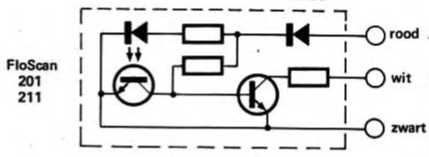
The output is open collector, so you need a resistor between the white wire and the 5V of your Arduino (if your Arduino is operating at 5V and not 3.3V). That resistor is called a pull up resistor because it pulls the output up to the supply voltage when the transistor is turned off.
If you go with 32,000 pulses per gallon and 1 gallon of liquid passes through the sensor in 1 hour, then you should get a count of 32,000 pulses in 1 hour - just under 9 pulses per second. Of course, a higher flow rate = more pulses per second.
An Arduino UNO has a built-in hardware counter that you can use to count pulses. You could query the counter once per second and use that to extrapolate to gallons per hour.
Perfect I will check which variant i have, i understood everything but Im not sure about how the build in arduino hardware counter works, do you have any rtaccomended documentations i could check to see hwo it works ?