Hey, i have this potentiometer which connects to arduino as an input and after that i want to check the output signal voltage using another arduino that has voltage sensor, when i check the output voltage using multimeter by positive to the positive output and signal output to the com on the multimeter, it reads about 2.5v ish but if i use another arduino that has voltage sensor, the arduino reads as 5v+ ish. Why doesn't the voltage sensor read about 2.5v ish? , if i use the voltage sensor on things like battery, it reads just fine, anyone know the problem?
Welcome to the forum
More details please of the Arduino boards that you are using, the sketches that you are running and a schematic (a picture of a hand drawn circuit is good enough) of how the boards are connected and powered
I use this code for the voltage sensor using arduino nano
// Define analog input
#define ANALOG_IN_PIN A0

// Floats for ADC voltage & Input voltage
float adc_voltage = 0.0;
float in_voltage = 0.0;

// Floats for resistor values in divider (in ohms)
float R1 = 30000.0;
float R2 = 7500.0;

// Float for Reference Voltage
float ref_voltage = 5.0;

// Integer for ADC value
int adc_value = 0;

void setup()
{
   // Setup Serial Monitor
   Serial.begin(9600);
   Serial.println("DC Voltage Test");
}

void loop(){
   // Read the Analog Input
   adc_value = analogRead(ANALOG_IN_PIN);

   // Determine voltage at ADC input
   adc_voltage  = (adc_value * ref_voltage) / 1024.0;

   // Calculate voltage at divider input
   in_voltage = adc_voltage / (R2/(R1+R2)) ;

   // Print results to Serial Monitor to 2 decimal places
  Serial.print("Input Voltage = ");
  Serial.println(in_voltage, 2);

  // Short delay
  delay(500);
and for the potentiometer i use arduino mega 2560 with input on A0 and output on D3
when i measure this output signal by multimeter it reads about 2.5v ish but when i use voltage sensor to read this, it goes to 5v ish
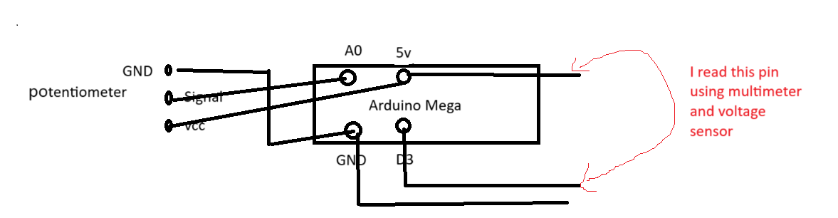
this is roughly the wiring, sorry for the bad drawing
and i use my laptop usb to power both the mega 2560 and nano, i dont know if it matter but maybe?
Hi,
Welcome to the forum.
Where in our code do you use D3 pin?
What voltage sensor?
Thanks... Tom.. ![]()
![]()
![]()
![]()
Hi Tom, for the arduino mega code, i use this code
/*
duty cycle in arduino is represented by a 8 bit value: 0 - 255
0 --> 0%
127 -->50%
255 --> 100%
*/

#define pwm1 3
#define pot A0
//#include <Wire.h>
//int duty = 0;

void setup() {
  // put your setup code here, to run once:
  pinMode(pwm1,OUTPUT);
  pinMode(pot,INPUT);
 // Wire.begin();
  Serial.begin(9600);
  //safety speed reset of the motor
  analogWrite(pwm1,0);

}

void loop() {
  // put your main code here, to run repeatedly:
  int val = analogRead(pot);
  int duty = map(val,0,54,28,255);
  analogWrite(pwm1, duty);
  //here's how to generate PWM signal from Digital arduino pin
  //analogWrite(pwm1, duty);
  //Serial.write(duty);
 // Wire.beginTransmission(4);
 // Wire.write(duty);
  //Wire.endTransmission();
  Serial.println(val);
  //delay(1000);
}
for the voltage sensor i use this kind of sensor, connects to arduino nano

Do you know that you have D3 of the Mega connected directly to GND of the nano?
Hi Jim,
No the nano and the mega are separate, nano is standalone acts as voltage sensor
Connected to separate computers/laptops?
Well they are separate but i power them using the same laptop by connect them to the usb ports, maybe that is the problem?
Yes it's a problem because the grounds of the UNO and Mega will be connected together through the USB ports.
However even if you connect them to separate laptops, the circuit will still not work.
Exactly what are you trying to do?
Why don't you just read the voltage between D3 and GND?
I am trying to record the output signal voltage, when i used multimeter for this it shows 2.5vish but the nano shows 5vish, when i use multimeter on the D3 and GND pin, the multimeter doesnt show anything
It's a PWM signal, your miltimeter probably can't read signals at the PWM frequency
It's a PWM signal, so the output voltage will either be 0V or 5V. Are you trying to record the average voltage?
I have moved this topic to Project Guidance....General Discussion didn't seem suitable for the questions.
Oh, so thats why, thanks Jim, by the way what do you mean by average voltage?
A 0V to 5V pwm signal with a 50% duty cycle will have an average voltage of 2.5V (0.5 x 5V)
The average voltage will = (duty cycle/100) x 5V
Oh yes, i think that is what i want to record, so should i just put another output pin and use the (duty cycle/100) x 5V as the code?
Here's a better way to do it and you don't need the voltage sensor board:
Connect the Mega D3 to the nano D8 (or any digital pin) through a 1K ohm resistor.
Use unsigned long pulse_width = pulseIn (D8,HIGH) to measure the pulse width.
Dutycycle = (pulse_width x 590.0)/1000000.0.
Average voltage = 5 x Dutycycle