Hi, I'm trying to use a reprap StepStick with an Arduino Uno R4 Wifi to drive a Nema 17 motor.
At the moment I'm fairly confident in my code, and checking the output pins of the Arduino everything seems normal.
Where I think I'm having an issue is with the driver board. I'm using a 5A, 12V brick to power it, but following this guide I can't set VRef. Even if I turn the pot all the way clockwise, I only get a Vref of 0.24V. Does anyone have a clue what might be happening? Everything is on a breadboard at the moment. I've checked What I can with a MM and scope but my knowledge has reached it's limit.
Such statements show that you are not very ready for advice and are unlikely to encourage those who want to help you.
I advise you to read the forum guidelines again and think about whether you asked your question correctly.
My issue here is before I even run the code, so I am not asking in reference to that. I have my driver hooked up as here.
The Vref I am measuring does not make sense to me according to the tutorials I have read.
VMOT must be greater than 8V.
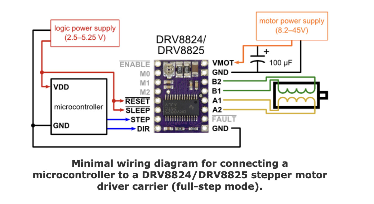
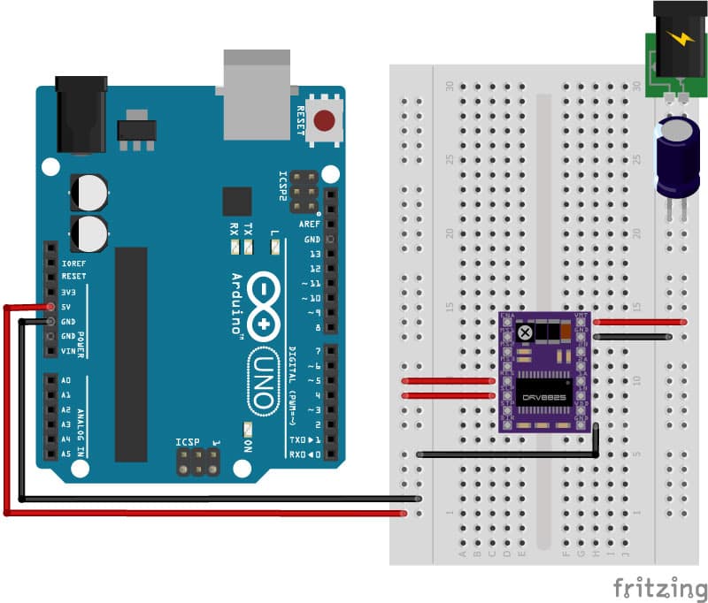
It should be connected as shown here
1 Like
Which one?
They can come with different sense resistors and need different formulas.
You need to find the Vref calculation specific for your board, it varies by chip and also what sense resistor is on the board.
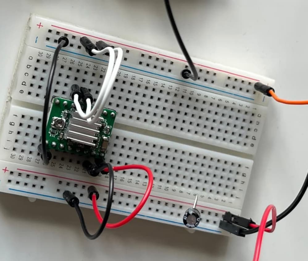
Thanks for the tips everyone. I'm fairly sure I have the standard 1A, but I will double check. Here's my wiring setup:

I stuck a scope on the Pot to see if it was really a DC signal:
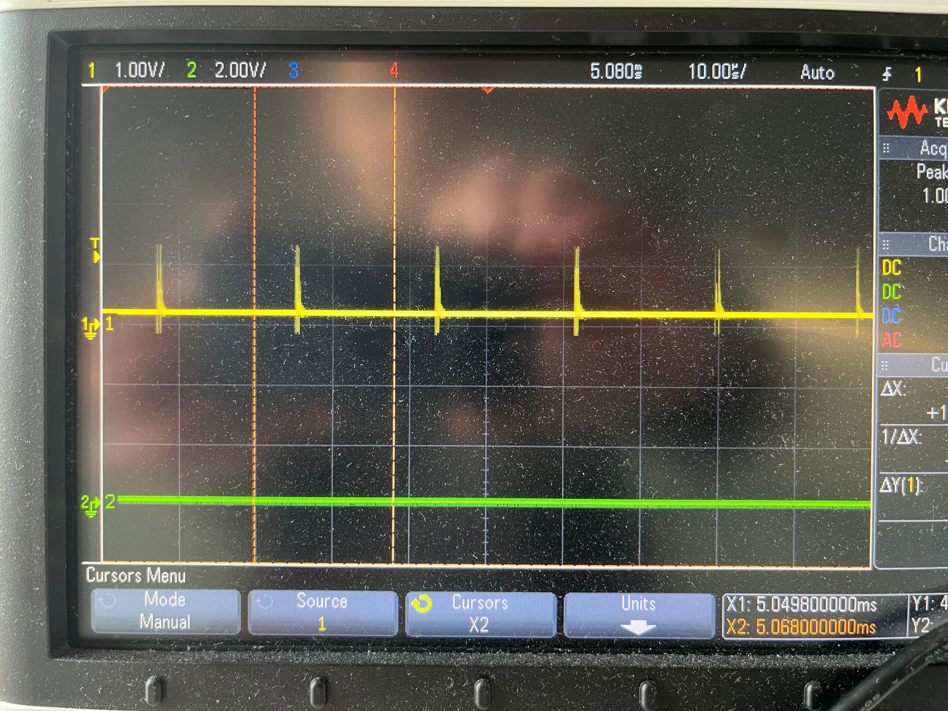
There's the 0.2V DC, but also 1.2V spikes at 55kHz.
That seems too low, regardless of other factors. With a trim pot of 10k and fixed resistor of 20k, you should get a range of 0 - 1.6 V. The 1.5 A version should have a range of 0-1.25V.
If you are not seeing that range, perhaps the board is bust. Those little trimpots are not very robust. Also note that some do not have endstops, and can rotate past the end of the track. I would normally put the pot in the center position and multiply by 2 to get the max range.
The 55kHz spikes are probably related to PWM crosstalk from the driver, I wouldn't worry too much about those (although perhaps could also indicate a fault, but I never tried putting a scope on the trimpot).
1 Like
No, I get 0.8V with 5V spikes at that same 55kHz.
I checked the sense resistors and they are 0.2ohm, so I have the 1A board.
I meant: do you connect a 5V source to VDD? It doesn't look like you do from the picture.
0.24V/0.8V=0.3 and 0.3*5V=1.5V -- I think your trimpot is working as designed, but the 0.8V measured at VDD is coming from some unreliable parasitic source.
VMOT must be > 8V
reset and sleep need to be connected as shown
Vmot is 12V, as I stated in the first post. Reset and sleep are connected to 5V.
None of the tutorials I've read have mentioned the need to connect VDD to 5V for setting the Vref. Do you have a source for this?
This:
And the Pololu link (as from #4):

Power connections
The driver requires a logic supply voltage (3 V to 5.5 V) to be connected across the VDD and GND pins and a motor supply voltage (8 – 35 V) to be connected across VMOT and GND. These supplies should have appropriate decoupling capacitors close to the board, and they should be capable of delivering the expected currents (peaks up to 4 A for the motor supply).
1 Like
See post #4
Follow the instructions as I suggested
1 Like
Oh, I see -- a "RepRap StepStick" is different than an 8825 driver, and the tutorial you linked is for an 8825. The StepStick uses an A4988.
Which do you have?
Well there we go, problem solved. Thanks everyone. 5V to VDD gave sensible readings for Vref. Load up a basic stepper code and voila, it spins. ![]()
1 Like
As explained way back in post #4
"explained" is doing a lot of heavy lifting there Jim. You made an irrelevant statement about Vmot and linked to the Pololu website. Thanks for trying to help nonetheless.