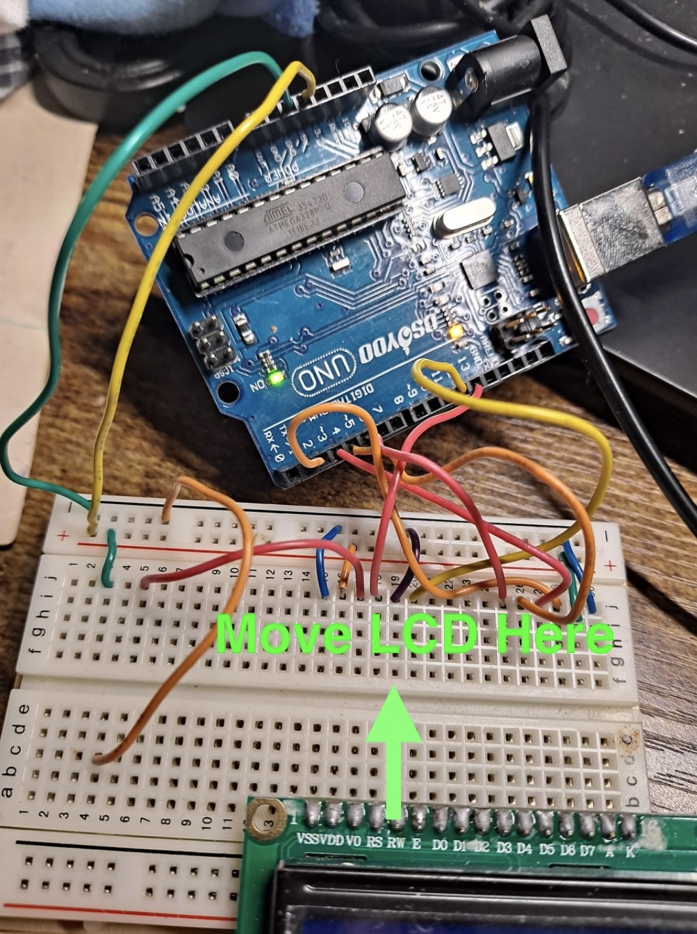
Water level sensor, no signs of life, bread board powered, potentiometer woes

First of all, I am pretty new to beginner electronics and Arduino. I've completed a few small projects like getting an LED to light up (making sure to use a resistor, I learned the hard way...very loud POP! when the LED burned out!). I also completed one of the beginner projects where you pinch a temperature sensor and you can watch the LEDs progressively light up or turn off as the temperature rises and falls.

This time around I am attempting a more ambitious project. I am trying to create a water level sensor for our dog's water bowl. We do pretty good about keeping on top of it, but this was an excuse to get back into Arduino again after a few years break.

I am using an older Arduino UNO board by Osoyoo. I believe it is an "R2"?. I will be providing a picture and if it is allowed, a small video clip here in a minute.

I have not added the water sensor yet. I decided I wanted to first get the 32 character LCD output working (the one with 16 chars x 2 rows?)

I followed the following tutorial I found at random on Geek Pub during a google search:

I tried to very carefully follow the tutorial step by step.

I have some questions besides the obvious one: How can power the LCD so it can receive and output something...anything?

Secondary questions are: How do I verify the Potentiometer is working? Must I have one? If I don't have one what will happen? Alternatives to using one?

In my ignorance, I used the little "hex tool" provided to modify the Potentiometer and turned it all the way to the right to see what would happen...and it started smoking. I hope to God I didn't damage the LCD screen. Luckily I have a spare.

Here is the code (basically the code that is available in the tutorial):

// include the library code:
#include <LiquidCrystal.h>;
//initialise the library with the numbers of the interface pins
LiquidCrystal lcd(12, 11, 5, 4, 3, 2);
 
void setup() {
// set up the LCD's number of columns and rows:
lcd.begin(16, 2);
 
// Print a message to the LCD.
lcd.print("The Geek Pub!");
}
 
void loop() {
// set the cursor to column 0, line 1
lcd.setCursor(0, 1);
 
// print the number of seconds since reset:
lcd.print(millis() / 1000);
}

Follow the tutorial.

The LCD only receives and displays characters that your sketch sends to it via "lcd.print()" commands.

The picture of your LCD in a breadboard has the LCD on the wrong side of the median to connect to the wires through the breadboard.

Your code works. Just verify your wiring.

wokwi.com sketch.ino
// include the library code:
#include <LiquidCrystal.h>;
//initialise the library with the numbers of the interface pins
LiquidCrystal lcd(12, 11, 5, 4, 3, 2);

void setup() {
  // set up the LCD's number of columns and rows:
  lcd.begin(16, 2);

  // Print a message to the LCD.
  lcd.print("The Geek Pub!");
}

void loop() {
  // set the cursor to column 0, line 1
  lcd.setCursor(0, 1);

  // print the number of seconds since reset:
  lcd.print(millis() / 1000);
}
wokwi.com diagram.json
{
  "version": 1,
  "author": "Anonymous maker",
  "editor": "wokwi",
  "parts": [
    { "type": "wokwi-arduino-nano", "id": "nano", "top": -4.8, "left": 28.3, "attrs": {} },
    { "type": "wokwi-lcd1602", "id": "lcd1", "top": -169.37, "left": -12.8, "attrs": {} }
  ],
  "connections": [
    [ "lcd1:RS", "nano:12", "green", [ "v0" ] ],
    [ "nano:11", "lcd1:E", "green", [ "v-28.8", "h9.6" ] ],
    [ "lcd1:D7", "nano:2", "green", [ "v0" ] ],
    [ "lcd1:D6", "nano:3", "green", [ "v0" ] ],
    [ "lcd1:D5", "nano:4", "green", [ "v0" ] ],
    [ "lcd1:D4", "nano:5", "green", [ "v0" ] ]
  ],
  "dependencies": {}
}

The instant I moved the LCD board to the other side of the ... bridge? ..... it immediately lit up.

So that answers THAT. : ) Thank you so much.

So is it likely the Potentiometer will also work, once I get it moved over to the other side of the "bridge" as well?

My wife refers to those as tLEDS "temporary Light Emitting Diodes". And you can also make one with a small signal diode (1N4148 for example) directly across the power supply. :slightly_smiling_face:

YES, the pins on the one side of the gutter are not connected to the other side. Some boards even split the power rails down the edges at the halfway point. That catches a few new folks and even us oldies. You can see the red line and black or blue break at the halfway point. Some boards do not do that.

: ) nice!

That tells me you connected it wrong and it is now probably a crispy critter. The LCD is powered via the segment lines, the Vcc or ??? is for the LED. Ground is the reference and used by all.

Noted!!

What's funny is these mistakes teach me every bit as much as the successes.

  • Experience varies directly with equipment ruined. :roll_eyes:

  • You can wire the potentiometer as seen below.
    Both outer leads going to GND.

Having both ends of r1 connected to vss you won't be able to trim the contrast of the lcd.
Instead connect one end to vss and the other to vdd.
To trim the contrast when there is nothing written on the lcd ( but the lcd is powered on vss-vdd ) rotate the trimmer from one side to the other, until the background is fully visible, then turn back a little bit ( background should be faint or not visible at all )

addition
Also before connecting backlight ( generally pins 15, 16 ) to vdd and vss directly, check the lcd has an onboard limiting resistor, if not add one externally to limit the current to a safe value ( or you risk to 'puff' the backlight )

Why don't you do everything exactly as they do in the tutorial

  • Connecting both outer leads of the potentiometer to 0v (Vss) works fine.

I understand the crispy critter part.

But I am not sure I understand the rest of what you said.

0v? (Vss) ?

0v meaning the ground?

(Vss) means???

Now that somebody clued me in on the "bridge" part of the breadboard, I plan to do just that.

It may be a day or so before I can come back and report.

I was asking how you powered the display. @LarryD diagram should do it for you.

a limiting resistor? What would it look like?

How would I add a limiting resistor externally and what kind would it be in order to limit the current to a save value?

What do potentiometers do? I haven't had time to research that part of the project.

Doing it exactly also means placing the parts the same way