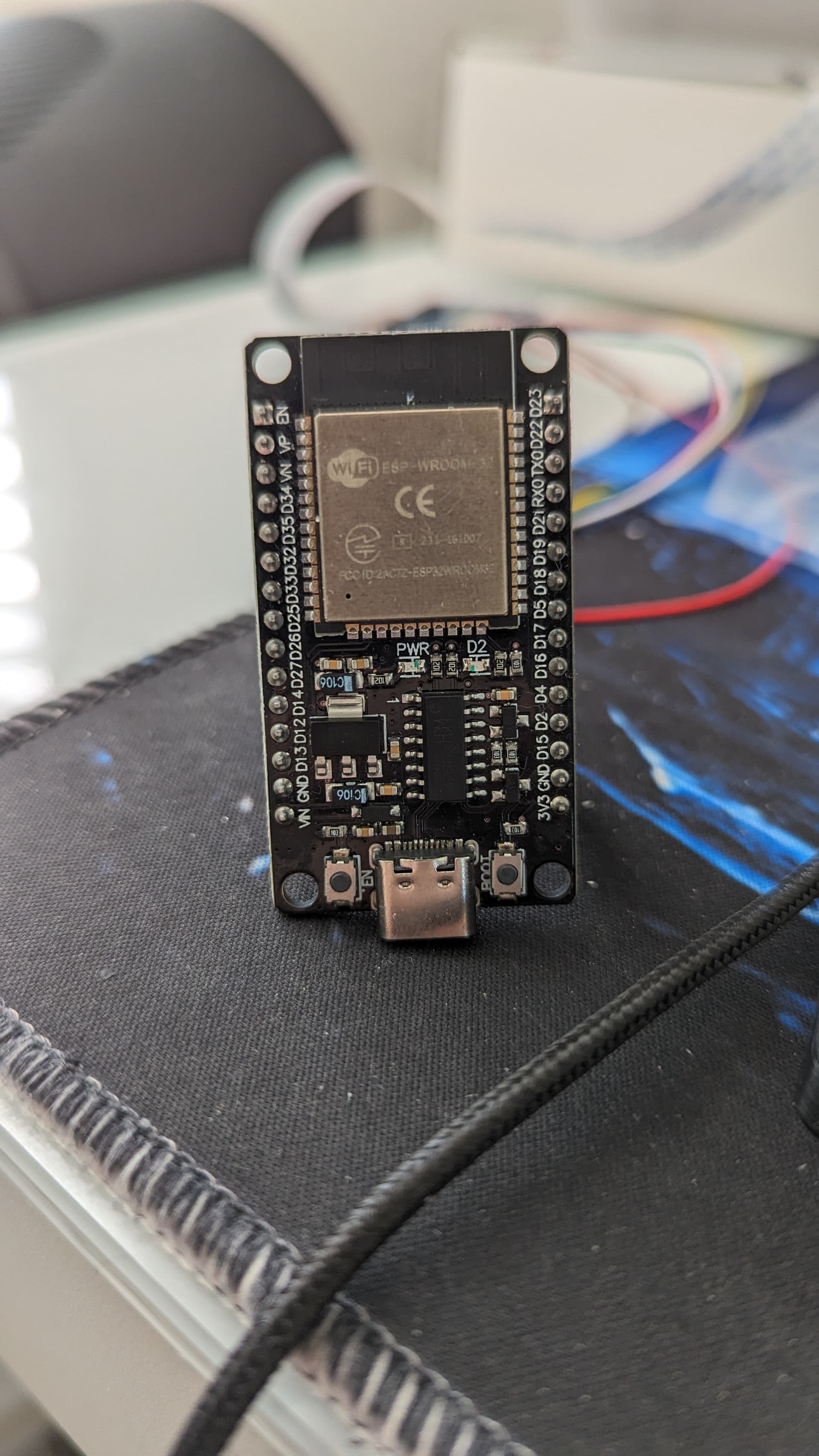
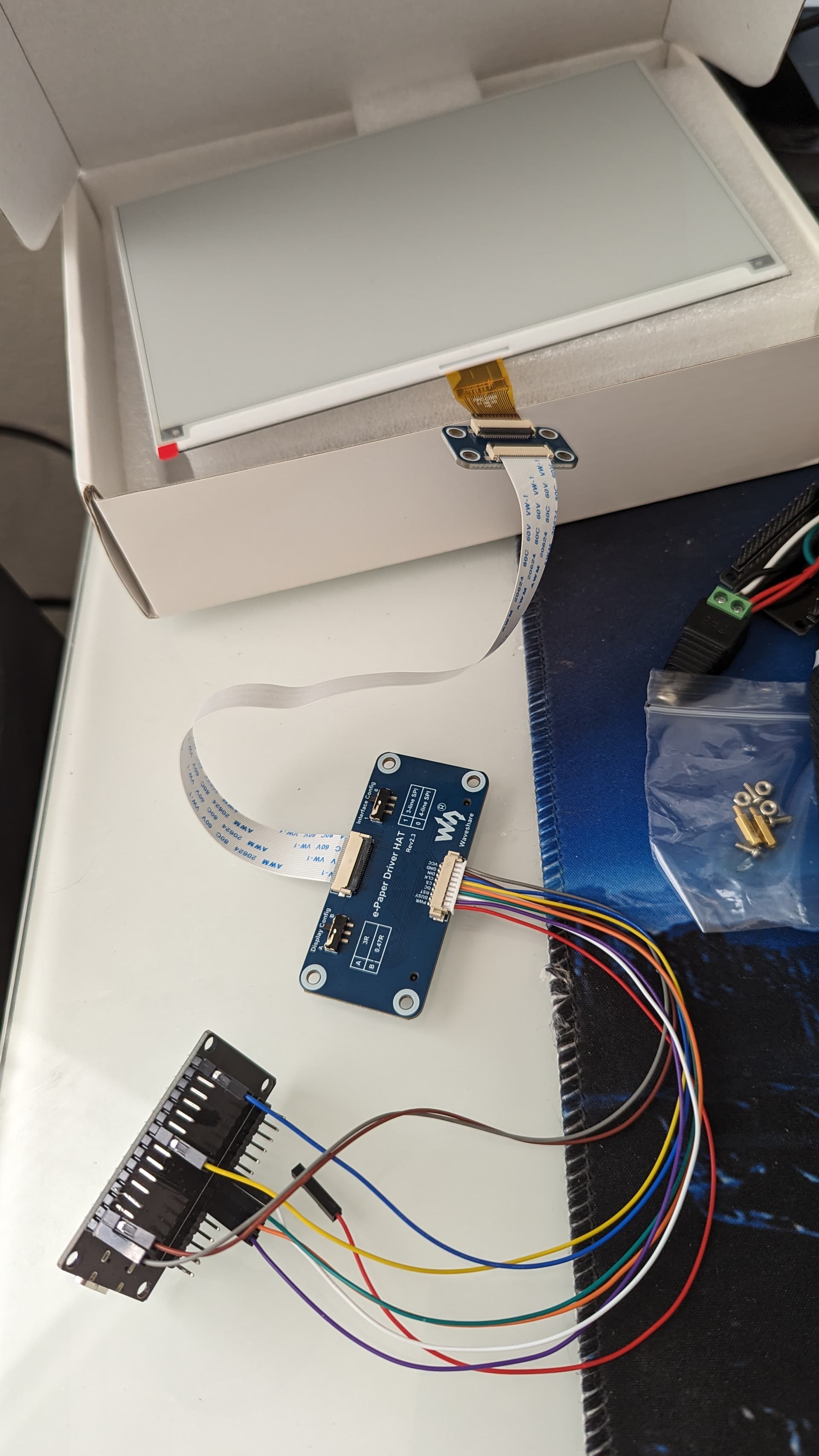
Hi, I recently bought a Waveshare 7.5in V2 E-ink display with raspberry pi hat (v2.3) and I cannot get it to work with an esp32 ( I believe its a Nodemcu one but it's unlabeled so IDK)
I have tried multiple different wiring configs and multiple different example sketches as well as trying esphome, the error message I received from esphome is "[waveshare_epaper:167]: Timeout while displaying image!" Also can ribbon cables be plugged in either orientation, or is it a single set direction?
This is also mentioned briefly on the wiki, but not very clearly:
If you want to upgrade the version, you can choose one of the following ways:
Update the program to the newest one (Arduino program only supports 7.5inch e-Paper, 7.5inch e-Paper (B), 5.83inch e-Paper, 5.83inch e-Paper (B), 2.9inch e-Paper (D), 2.13inch e-Paper (D)).
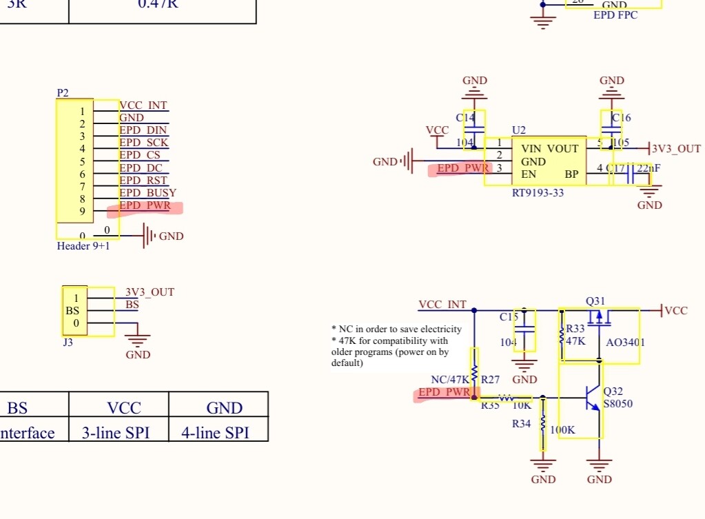
Connect PWR pin to 3.3V.
The empty pad on the back side is soldered with a 47K (or similar) resistor.
@purerandom - is that working for you? I have similar situation but my ESP32 has only one 3.3V pin, probably like yours. What pins exactly did you use to make it working? I took this connection scheme:
So it turns out that the PWR pin does need to be connected to power/3.3v for it to work, so try powering the PWR pin and see what happens, that is what fixed it for me.
I connected the PWR pin to 3.3V so that now I have both 3v3 and PWR connected to one 3.3V pin since the board has only one 3.3V pin.
VCC remains unused for now as I'm powering the board from USB port.