I'm stuck while setting up my Waveshare 7.5 Inch E-Paper Display HAT Module V2 to work with my ESP32 Dev Kit C V2 from AZ-Delivery.
I already followed multiple tutorials but could not get a single Pixel to show up.
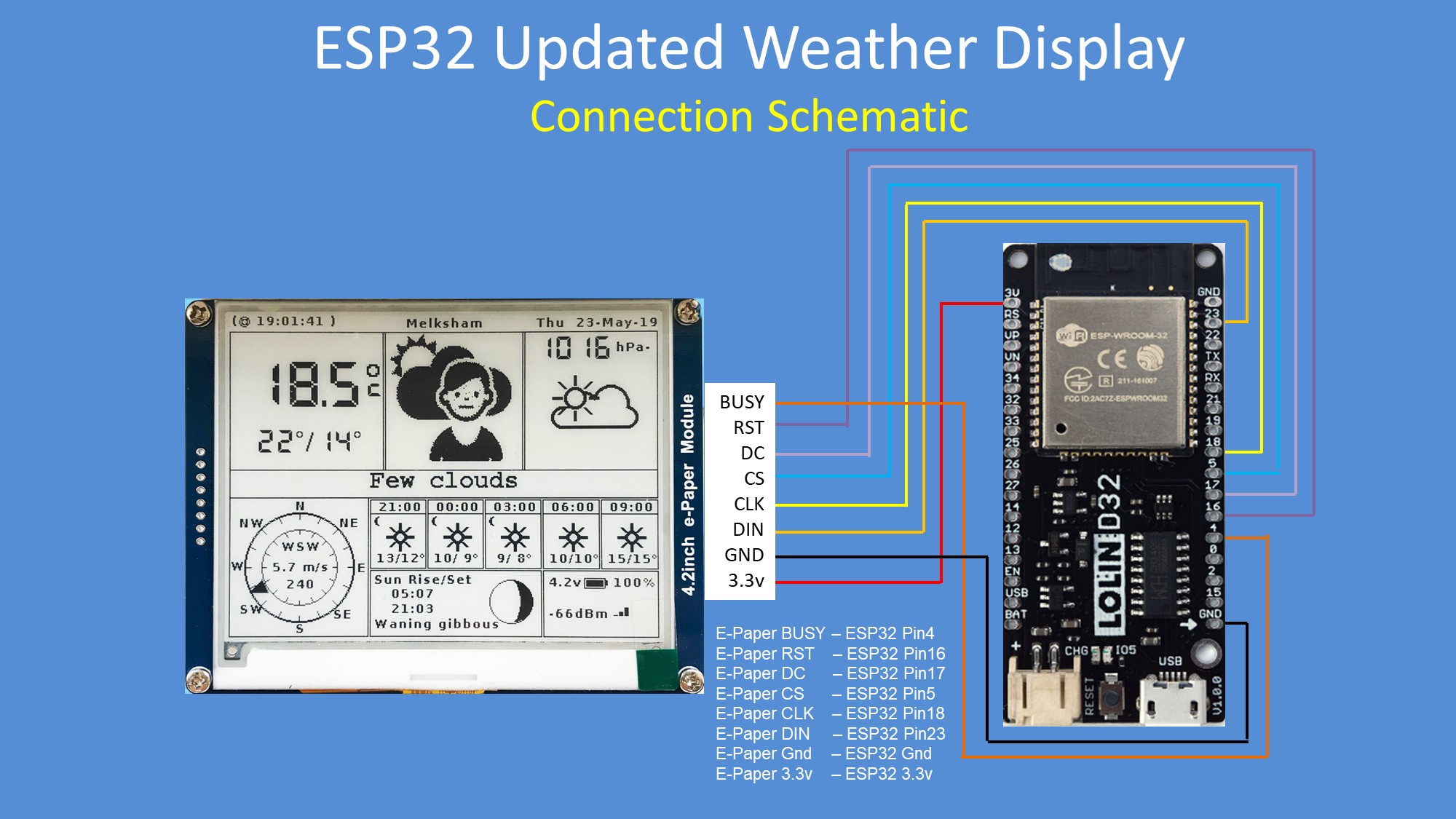
The images show my setup and cabling.
Basically, I have the following questions:
Is there anything I could do wrong (not connecting the display properly?)
And how may I validate that the connection is correct?
Which setting should I choose on the HAT Module?
I can choose between 3-line SPI and 4-line SPI (currently)
and between 3R and 0.47R (currently)
Within the Code example on the Waveshare website the code get's stuck in epd.Init()
How can I debug this further to see what is causing the issue?
I also tested the GxEPD2 library, of course. Unfortunately, this had no success either.
Here's the demo code from Waveshare, that I used:
Congratulation for providing this much information with your first post.
For further posts in the Displays section, I suggest you provide clickable links to the devices in question, e.g. 800×480, 7.5inch E-Ink display HAT for Raspberry Pi SKU: 13504.
4-line SPI and 0.47R are correct. (3-line SPI is hard to use. Consult panel specs for RESE value.)
I use to add Serial.print() statements to pinpoint were a program gets stuck, when I am desperate.
Your picture shows a newer panel than the one shown on the Waveshare page.
It seems to have the same inking as my GDEY075T7 I am working on just now.
It almost works with the same driver as for GDEW075T7, with some distortions.
The wiring used by G6EJD for ESP32 is the same I suggest for GxEPD2, which comes to no surprise.
Still does not seem to work.
I also tried it with your library and suggested wiring. Also no change on the display.
As long as the simplest (Waveshare) demo does not seem to work, I'm afraid of testing further libraries.
I use to add Serial.print() statements to pinpoint were a program gets stuck, when I am desperate.
But I would need them within the used libraries, don't i?
Is there anything else that I might not do correctly?
I checked the PH2.0 and Display Connectors multiple times. A very small LED indicating "power" would help a lot in that scenario.
On the schematics you can see that the VCC_int pin of the 6-pin connector goes through a
MOS FET to an LDO. If 3.3V is connected to VCC_int, the 3V3_out may be too low for the e-paper controller to get ready. And the "clever" reset circuit, driving the MOS FET may worsen things.
You could connect 5V to VCC_int, but then you need a series resistor on the BUSY line, e.g. 10k, to protect the ESP32.
And / or you could add a pull-up resistor on RST, 4k7 ... 10k.
I don't have this actual HAT, so I can't try.
Yes, you would. But you would only find out that is waiting indefinitely for BUSY to become inactive.
Ok, so far as I understand, the voltage seems to be too low to activate the BUSY line.
I measured the voltages and as expected the BUSY line is always LOW.
However, the RST seems to have about 3.3V constantly.
I shorted the BUSY line a few times and the code runs to "Image ready!" here:
void setup() {
  pinMode(4, INPUT);
  // put your setup code here, to run once:
    Serial.begin(115200);
    Epd epd;
    Serial.print("initializing...");
    if (epd.Init() != 0) {
        Serial.print("e-Paper init failed");
        return;
    }
    Serial.print("running!");
    //epd.Clean();
    epd.DisplayOneQuarterFrame(IMAGE_DATA);
    Serial.print("Image ready!");
}
But it still does not show any image (since the BUSY line was not truly HIGH, I suppose)
I need to get some resistors and will try to run it like you said.
I can take the 5V from the ESPs dedicated PIN, right?
Yes, you can take it from the ESP32 5V pin. It is from USB 5V, through a diode, I think.
The e-paper controller (UC8179) generates and checks the panel driving voltages from its 3.3V supply. On the big e-paper displays it may not reach the required driving voltage, if the 3.3V supply is too low or weak. This might also be caused by a weak LDO on the processor board, or a low or weak USB supply. You can also try to connect to a USB 3 connector on your PC or notebook.
So it's either the USB supply which is too weak ( I already tried to power it with a power bank and other USB ports) or I'm missing something absolutely fundamental.
I can only try to put a serial resistor on RST as you suggested.
Ok, then I suggest you try with GxEPD2, and report diagnostic output from Serial Monitor.
In GxEPD2_display_selection_new_style.h of GxEPD2_Example select (uncomment) this line:
Do you mean Waveshare boards that have the "clever" reset circuit?
I think all e-paper boards and e-paper connection boards now have it, except the ESP8266 and ESP32 E-Paper Driver boards.
I should have immediately thought of this, as other users had the same issue, but I was distracted by my current work.


