I have a strange situation with an I2C INA219 current/volt meter module.
In front of me, I have a rather scary 16.8V lipo - its positive output is on the VIN+ of the INA219.
The VIN- leads off to a big chunky switch, which leads off to an XL4015 DC-DC, set to 5V output. Its output reads 5.02V, with no load. Power for the UNO is obviously coming from the USB port of my laptop. The battery ground of is not connected to the UNO ground, but the GND of the sensor module is, as prescribed.
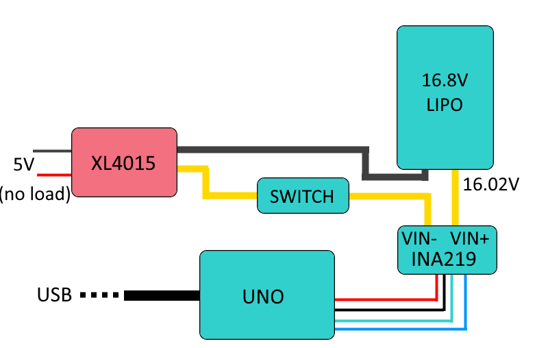
Switching the XL4015 on or off does not affect the battery output leading to the INA219 input, which reads as 16.03V. The INA219 sensor is happily connected, (SCL-SDA-GND-VCC heading off to an Arduino UNO) and is giving readings to the UNO.
Its just that they are wrong. I'm obviously very interested in getting hte 16.8V battery voltage, but the reading is something weird, like 1.08V. A multimeter says otherwise, as I said.
Serial output:
Bus Voltage: 1.08 V
Shunt Voltage: 1.25 mV
Load Voltage: 1.09 V
Current: 12.60 mA
Power: 14.00 mW
Below is the code:
#include <Wire.h>
#include <Adafruit_INA219.h>
Adafruit_INA219 ina219;

void setup(void)
{
  Serial.begin(115200);
  }
  uint32_t currentFrequency;
  ina219.begin();
}

void loop(void)
{
  float shuntvoltage = 0;
  float busvoltage = 0;
  float current_mA = 0;
  float loadvoltage = 0;
  float power_mW = 0;

  shuntvoltage = ina219.getShuntVoltage_mV();
  busvoltage = ina219.getBusVoltage_V();
  current_mA = ina219.getCurrent_mA();
  power_mW = ina219.getPower_mW();
  loadvoltage = busvoltage + (shuntvoltage / 1000);

  Serial.print("Bus Voltage:   "); Serial.print(busvoltage); Serial.println(" V");
  Serial.print("Shunt Voltage: "); Serial.print(shuntvoltage); Serial.println(" mV");
  Serial.print("Load Voltage:  "); Serial.print(loadvoltage); Serial.println(" V");
  Serial.print("Current:       "); Serial.print(current_mA); Serial.println(" mA");
  Serial.print("Power:         "); Serial.print(power_mW); Serial.println(" mW");
  Serial.println("");
  delay(2000);
}
The connections should be super dumb obvious, but I am dumb, apparently, or I've got a dud sensor. Yet that 12mA looks about right, so the current sensing bit seems to be doing its thing. Voltage reading though....
Any ideas?