Hi! I'm a beginner in the world of Arduino and have recently started to create some projects.
I recently purchased an RFID scanner kit along with some tags and cards. I have used this RFID before and it has worked completely fine with an Arduino Uno.
In my latest project, I want to connect the same RFID scanner to an Arduino Mega. However, I always get the same error every time I upload the DumpInfo code: Firmware Version: 0x18 = (unknown).
When I connect the same RFID scanner to an Arduino Nano, I get the same error. However, the Arduino Nano is capable of reading the cards and tags and even outputs this information to the Serial monitor. The arduino mega does not read anything. I thought this behaviour was weird (yes, I did change the values of the constants in DumpInfo for both the boards). Is this some programming fault or is it some issue with the Mega?
/*
 * --------------------------------------------------------------------------------------------------------------------
 * Example sketch/program showing how to read data from a PICC to serial.
 * --------------------------------------------------------------------------------------------------------------------
 * This is a MFRC522 library example; for further details and other examples see: https://github.com/miguelbalboa/rfid
 *
 * Example sketch/program showing how to read data from a PICC (that is: a RFID Tag or Card) using a MFRC522 based RFID
 * Reader on the Arduino SPI interface.
 *
 * When the Arduino and the MFRC522 module are connected (see the pin layout below), load this sketch into Arduino IDE
 * then verify/compile and upload it. To see the output: use Tools, Serial Monitor of the IDE (hit Ctrl+Shft+M). When
 * you present a PICC (that is: a RFID Tag or Card) at reading distance of the MFRC522 Reader/PCD, the serial output
 * will show the ID/UID, type and any data blocks it can read. Note: you may see "Timeout in communication" messages
 * when removing the PICC from reading distance too early.
 *
 * If your reader supports it, this sketch/program will read all the PICCs presented (that is: multiple tag reading).
 * So if you stack two or more PICCs on top of each other and present them to the reader, it will first output all
 * details of the first and then the next PICC. Note that this may take some time as all data blocks are dumped, so
 * keep the PICCs at reading distance until complete.
 *
 * @license Released into the public domain.
 *
 * Typical pin layout used:
 * -----------------------------------------------------------------------------------------
 *             MFRC522      Arduino       Arduino   Arduino    Arduino          Arduino
 *             Reader/PCD   Uno/101       Mega      Nano v3    Leonardo/Micro   Pro Micro
 * Signal      Pin          Pin           Pin       Pin        Pin              Pin
 * -----------------------------------------------------------------------------------------
 * RST/Reset   RST          9             5         D9         RESET/ICSP-5     RST
 * SPI SS      SDA(SS)      10            53        D10        10               10
 * SPI MOSI    MOSI         11 / ICSP-4   51        D11        ICSP-4           16
 * SPI MISO    MISO         12 / ICSP-1   50        D12        ICSP-1           14
 * SPI SCK     SCK          13 / ICSP-3   52        D13        ICSP-3           15
 *
 * More pin layouts for other boards can be found here: https://github.com/miguelbalboa/rfid#pin-layout
 */

#include <SPI.h>
#include <MFRC522.h>

#define RST_PIN         5         // Configurable, see typical pin layout above
#define SS_PIN          53         // Configurable, see typical pin layout above

MFRC522 mfrc522(SS_PIN, RST_PIN);  // Create MFRC522 instance

void setup() {
	Serial.begin(9600);		// Initialize serial communications with the PC
	while (!Serial);		// Do nothing if no serial port is opened (added for Arduinos based on ATMEGA32U4)
	SPI.begin();			// Init SPI bus
	mfrc522.PCD_Init();		// Init MFRC522
	delay(5);				// Optional delay. Some board do need more time after init to be ready, see Readme
	mfrc522.PCD_DumpVersionToSerial();	// Show details of PCD - MFRC522 Card Reader details
	Serial.println(F("Scan PICC to see UID, SAK, type, and data blocks..."));
}

void loop() {
	// Reset the loop if no new card present on the sensor/reader. This saves the entire process when idle.
	if ( ! mfrc522.PICC_IsNewCardPresent()) {
		return;
	}

	// Select one of the cards
	if ( ! mfrc522.PICC_ReadCardSerial()) {
		return;
	}

	// Dump debug info about the card; PICC_HaltA() is automatically called
	mfrc522.PICC_DumpToSerial(&(mfrc522.uid));
}
GitHub - miguelbalboa/rfid: Arduino RFID Library for MFRC522
The above link is the link I followed for the pin layout. So far, I have only tested the DumpInfo file and nothing else. DumpInfo is provided by the library. This is the first step to my project
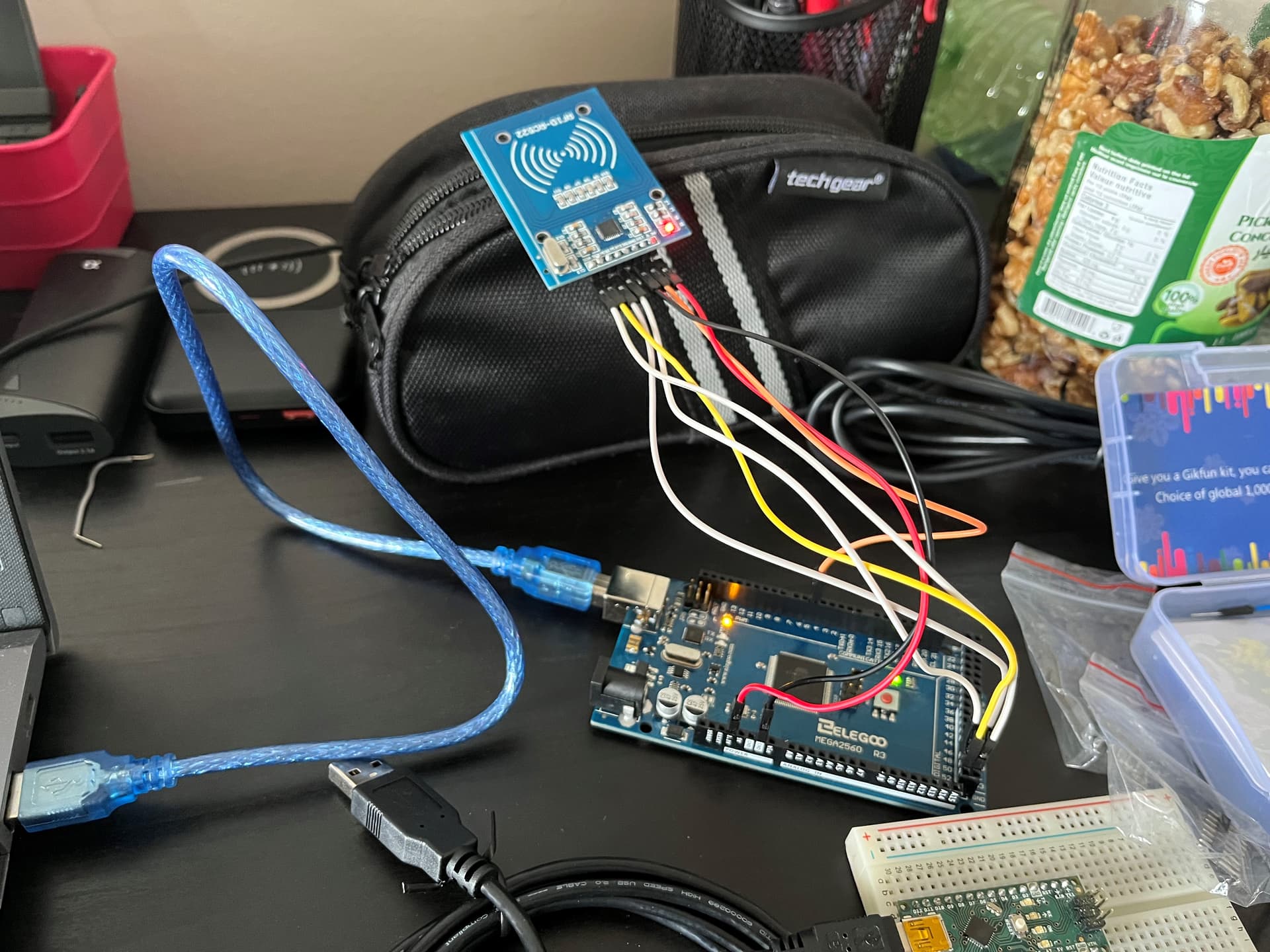
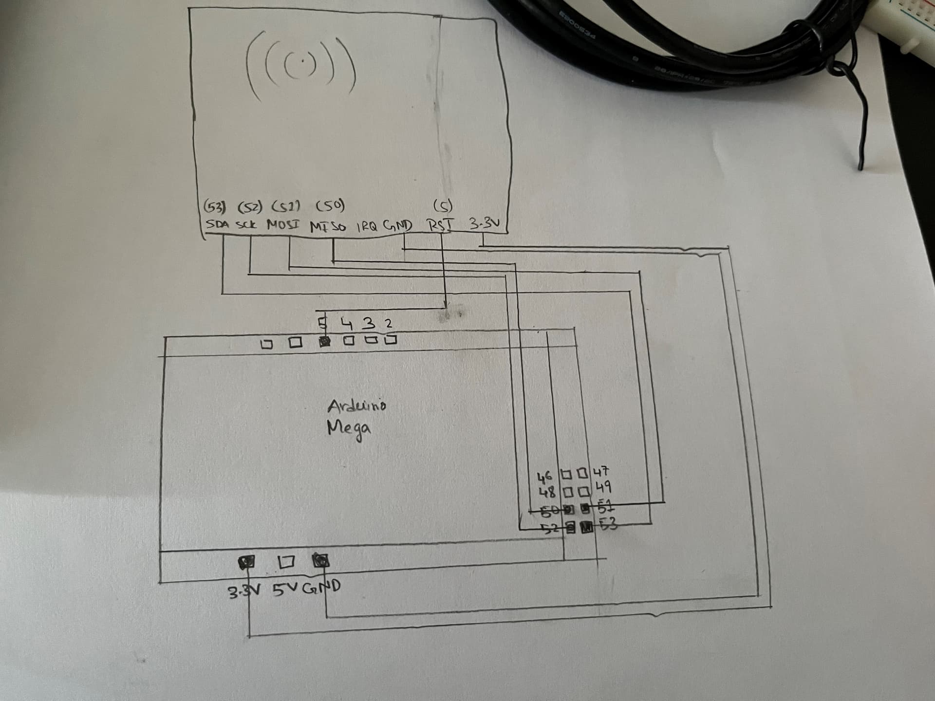
I think, under these circumstances, you should break out a pen and paper, and show us a diagram with all your connections. Pin lists are only sufficient for projects that are working. Unfortunately, the photo doesn't show the connections clearly enough to verify them visually.
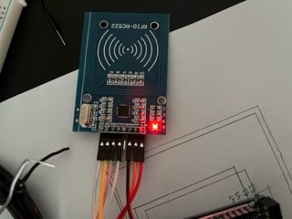
I tried the troubleshooting steps. The soldering is fine, the 3.3V is being powered correctly, the connections are all correct etc. If the RFID scanner is not working properly, then I don't understand how it is scanning teh cards properly when I rewire it and control it through an Arduino Nano.