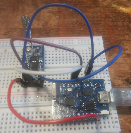
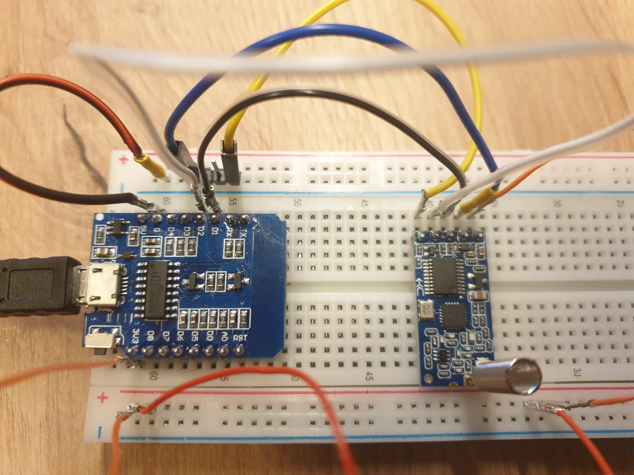
I'm struggling with a project using an HC-12 module and a Wemos D1. This involves an MHz transmitter and receiver.
My goal is to configure the module to operate on the 433.92 MHz frequency and then receive the data transmitted by my remote control. Ideally, the Wemos would also display the protocol and method used by the remote.
Unfortunately, I am already stuck with configuring the module in AT mode because I don't get an OK response. Here is my sketch:
I read that the SET must be set to HIGH, to setup the AT-Mode. in a other Datashett is called LOW....
#include <ESP8266WiFi.h>
#include <SoftwareSerial.h>

// WiFi-Zugangsdaten
const char* ssid = "xxxx";        // Dein WiFi-Name
const char* password = "xxxx"; // Dein WiFi-Passwort

// HC-12 Pins
#define RX_PIN D1  // RX von HC-12
#define TX_PIN D2  // TX von HC-12
#define SET_PIN D5 // SET-Pin des HC-12 für den AT-Modus

// SoftwareSerial für das HC-12
SoftwareSerial hc12(RX_PIN, TX_PIN);

// Funktionsdeklarationen
void checkHc12Response();
void connectToWiFi();

void setup() {
  // Serielle Kommunikation für Debugging
  Serial.begin(9600);
  delay(10);

  // Verbinde mit WiFi
  connectToWiFi();

  // Set-Pin auf HIGH setzen, um in den AT-Modus zu gehen
  pinMode(SET_PIN, OUTPUT);
  digitalWrite(SET_PIN, LOW); // AT-Modus aktivieren
  delay(3000);  // Eine längere Verzögerung, um sicherzustellen, dass der HC-12 im AT-Modus ist

  // HC-12 Initialisierung
  hc12.begin(9600); // HC-12 Baudrate im AT-Modus
  Serial.println("HC-12 im AT-Modus");

  // AT-Befehl: Testen, ob der HC-12 im AT-Modus ist
  hc12.println("AT");
  delay(3000);  // Warten, um eine Antwort zu erhalten
  // Gebe die Antwort des HC-12 aus
  checkHc12Response();

  // AT-Befehl zum Kanal setzen (z.B. 433,92 MHz Frequenz)
  hc12.println("AT+C001");  // Kanal 1 (433,92 MHz)
  delay(3000);  // Warten, bis die Antwort empfangen wird
  checkHc12Response();

  // AT-Befehl: Sendeleistung auf Mittelstellung setzen
  hc12.println("AT+P10");
  delay(3000);  // Warten, bis die Antwort empfangen wird
  checkHc12Response();

  // Set-Pin auf LOW setzen, um den AT-Modus zu verlassen
  digitalWrite(SET_PIN, HIGH); // AT-Modus verlassen
  delay(5000);  // Warte eine Sekunde, um sicherzustellen, dass der HC-12 den AT-Modus verlässt

  Serial.println("HC-12 konfiguriert und bereit.");
}

void loop() {
  // Wenn Daten im seriellen Monitor eingegeben werden
  if (Serial.available()) {
    String input = Serial.readStringUntil('\n'); // Liest die Eingabe
    Serial.print("Eingabe empfangen: ");
    Serial.println(input);  // Gebe die Eingabe im seriellen Monitor aus

    // Sende die Eingabe über das HC-12
    hc12.println(input);
  }

  // Wenn Daten vom HC-12 empfangen werden
  if (hc12.available()) {
    String receivedData = hc12.readStringUntil('\n');
    Serial.print("Empfangen von HC-12: ");
    Serial.println(receivedData);  // Gib die empfangenen Daten aus
  }

  delay(100);  // Kleine Verzögerung
}

// Funktion zur Überprüfung der Antwort vom HC-12
void checkHc12Response() {
 String response = "";
  while (hc12.available()) {
    response += (char)hc12.read();
  }
  Serial.println(response);
}

// Funktion zur Verbindung mit dem WiFi
void connectToWiFi() {
  // Verbinde mit WiFi
  Serial.println();
  Serial.print("Verbinde mit WiFi...");
  WiFi.begin(ssid, password);

  // Warten, bis die WiFi-Verbindung hergestellt ist
  while (WiFi.status() != WL_CONNECTED) {
    delay(1000);
    Serial.print(".");
  }

  // Erfolgreich verbunden
  Serial.println();
  Serial.println("Mit WiFi verbunden!");
  Serial.print("IP-Adresse: ");
  Serial.println(WiFi.localIP());
}
I moved your topic to an appropriate forum category @jumbo125 .
In the future, please take some time to pick the forum category that best suits the subject of your topic. There is an "About the _____ category" topic at the top of each category that explains its purpose.
initially test the ESP8266 <> HC-12 communications using a simple serial test
make sure you are using EspSoftwareSerial
// ESP8266 to HC-12 Software Serial test

// using library manager download and instal EspSoftwareSerial or instal ZIP
// https://github.com/plerup/espsoftwareserial

#include <SoftwareSerial.h>

// pins Rx GPIO5 (D1) and Tx GPIO 4 (D2)
SoftwareSerial swSer(5, 4);

// for HC-12 connect
// ESP8266 pin D2 TXD to HC-12 RXD
// ESP8266 pin D1 RXD to HC-12 TXD
// connect GND pins together and VCC to 3.3V
// for AT mode connect SET to GND else leave floating

void setup() {
  Serial.begin(115200);  //Initialize hardware serial with baudrate of 115200
  swSer.begin(9600);     //Initialize software serial with baudrate of 9600
  Serial.println("\nESP8266 Software serial test started");
  Serial.println("-  for loopback test connect pin D1 to pin D2\n");
}

void loop() {
  while (swSer.available() > 0) {  //wait for data at software serial
    Serial.write(swSer.read());    //Send data recived from software serial to hardware serial
  }
  while (Serial.available() > 0) {  //wait for data at hardware serial
    char ch = Serial.read();
    Serial.write(ch);      // uncomment if local echo required
    swSer.write(ch);        //send data recived to software serial
  }
}
when AT commands entered Serial Monitor displays (note SET is taken to GND)
ESP8266 Software serial test started
-  for loopback test connect pin D1 to pin D2

AT
OK
AT+V
www.hc01.com  HC-12_V2.4
AT+RX
OK+B9600
OK+RC001
OK+RP:+20dBm
OK+FU3
once that works you can start implementing the project
if you then type AT commands into the serial monitor (set baudrate to 115200 and line ending to Both NL & CR) it should echo the AT command and display any response
// ESP8266 to HC-12 Software Serial test

// using library manager download and instal EspSoftwareSerial or instal ZIP
// https://github.com/plerup/espsoftwareserial

#include <SoftwareSerial.h>

// pins Rx GPIO5 (D1) and Tx GPIO 4 (D2)
SoftwareSerial swSer(5, 4);

// for HC-12 connect
// ESP8266 pin D2 TXD to HC-12 RXD
// ESP8266 pin D1 RXD to HC-12 TXD
// connect GND pins together and VCC to 3.3V
// for AT mode connect SET to GND else leave floating

void setup() {
  Serial.begin(115200);  //Initialize hardware serial with baudrate of 115200
  swSer.begin(9600);     //Initialize software serial with baudrate of 9600
  Serial.println("\nESP8266 Software serial test started");
  Serial.println("-  for loopback test connect pin D1 to pin D2\n");
}

void loop() {
  while (swSer.available() > 0) {  //wait for data at software serial
    Serial.write(swSer.read());    //Send data recived from software serial to hardware serial
  }
  while (Serial.available() > 0) {  //wait for data at hardware serial
    char ch = Serial.read();
    Serial.write(ch);      // uncomment if local echo required
    swSer.write(ch);        //send data recived to software serial
  }
}
but i need to set it variable in AT mode. So i can't connect "set" to "gnd",
I need to set it to a pin, an change with LOW or HIGH the AT mode.
this don't work
#include <Arduino.h>

// ESP8266 to HC-12 Software Serial test

// using library manager download and instal EspSoftwareSerial or instal ZIP
// https://github.com/plerup/espsoftwareserial

#include <SoftwareSerial.h>
#define SET_PIN D5 // SET-Pin des HC-12 für den AT-Modus

// pins Rx GPIO5 (D1) and Tx GPIO 4 (D2)
SoftwareSerial swSer(5, 4);

// for HC-12 connect
// ESP8266 pin D2 TXD to HC-12 RXD
// ESP8266 pin D1 RXD to HC-12 TXD
// connect GND pins together and VCC to 3.3V
// for AT mode connect SET to GND else leave floating

void setup() {
  Serial.begin(9600);  //Initialize hardware serial with baudrate of 115200
  swSer.begin(9600);     //Initialize software serial with baudrate of 9600
  Serial.println("\nESP8266 Software serial test started");
  Serial.println("-  for loopback test connect pin D1 to pin D2\n");

  pinMode(SET_PIN, OUTPUT);
  digitalWrite(SET_PIN, LOW); // AT-Modus aktivieren
  delay(1000);
   // AT-Befehl: Testen, ob der HC-12 im AT-Modus ist
  swSer.println("AT");
  swSer.println("AT+C002");
  delay(3000);  // Warten, um eine Antwort zu erhalten
  digitalWrite(SET_PIN, HIGH); // AT-Modus aktivieren
  Serial.println("Fertig konfiguriert");
}

void loop() {
    if (swSer.available()) {
    String receivedData = ""; // Speicher für die empfangenen Daten

    // Lies die verfügbaren Daten
    while (swSer.available()) {
      char c = swSer.read();
      receivedData += c; // Zeichenweise speichern
    }

    // Gib die empfangenen Daten auf der seriellen Konsole aus
    Serial.println("Empfangen: " + receivedData);
  }
}
What's exactly"don't work "? The code doesn't print "OK" after your command?
In the code above you start to read hc-12's output too late to see an answer of the module.
it works now. The missing answer from the mhz module, is the failing protokoll.
it isn'T set for raw datas. sorry, its my fail.
so i will pay the fa1000
thank you fir your help