My reasoning: if we change Vcc, we get different Ic. If we change the resistors, we get different values across the entire circuit.
Ic(max) = Ib * β
Changing the voltage at the base without changing the resistor values will change the current of the base which changes the current that can flow through the collector too. Am I getting something wrong here?
So why exaclty is it called a constant current source, how should I interpret that name?
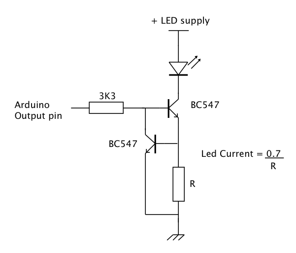
Re and the base voltage sets the collector current.
If you keep Vcc at a constant voltage and don’t change the base voltage divider then the emitter voltage stays the same.
If the voltage across the Re stays the same the emitter current stays constant.
If Rc is changed in value, the current through it still stays the same. Hence, we have a constant current source (within reason).
A better circuit would replace R2 with a zener diode.
If Vcc changes it is less likely to effect the constant current.
If Re was a potentiometer, changing the wiper position would allow you to have an adjustable constant current source.
This is a circuit that keeps a constant current "even if the load resistance was fluctuates" when using a fixed VCC.
VCC must be a fixed for standard uses.
I assume Vcc is supposed to remain constant. Then current through the load should remain constant when the load resistance is changed as long as the power supply voltage is high enough (per Ohm's Law) and as long as enough voltage is available. and not too much voltage is dropped across Re.
Transistors are current amplifiers. In the linear range, Collector-Emitter current is a multiple of base current. But in digital applications we often use transistors (and MOSFETs) as a switch (on/off) and in analog applications it's more common to use a circuit results in a voltage amplifier.
These days an LED is often used to create a voltage source of about 1.5 to 3V for the transistor base - voltage depending mainly on the LED colour. Can double as a power indicator, has better voltage regulation than two separate diodes.