I bought a few of these DPDT switches and as I'm a complete noob, which ohm resistor do I need. Thanks
Resistors are used to reduce the current flow. They help you to control the maximum current a device can handle. In your household you do not need a resistor between your light bulb and the switch (it would be counterproductive).
When attaching something to an Arduino output (using a switch) the minimum should be 220 ohms. If you use the switch to get positive/negative input a 10 kilo ohms resistor will do the job.
The higher the value, the less current you will get.
A switch is just a switch and does not require a resistor. However, the rest of your circuit might need resistors.
Switches themselves don't need any resistors.
If you are referring to arduino needing a pull up or pull down resistor to keep the input from floating to random values. There are 20k internal pull up resistors on each pin that can be enabled
By using the INPUT_PULLUP command.
If you want to use a separate resistor as a pull up or down use a high value such as 10-20k
If I didn't guess your intention you will have to be more clear.
Thanks for the reply, so would this work?
Black wire - GND
White wire - Digital input 2
Orange wire - 5V
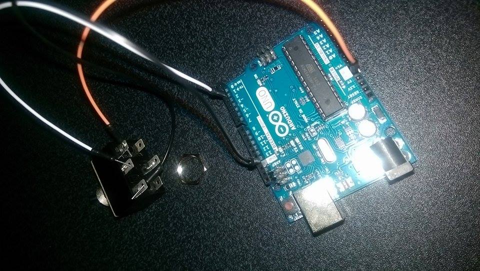
Yes, it does work. In your case you will switch the input voltage from GND to +5 Volts or vice versa. In INPUT mode the Arduino pins have a pretty high impedance and you do not need any protection using resistors.
Most switches have only 2 positions (on/off) and in this case you would need a pull-up/pull-down resistor to get a defined voltage at the input pin when the switch is open.
In your case the input always sees a fixed voltage (either 0 or 5 volts) because your switch has 3 pins. The center position is connected to the Arduino input, and the other two to GND and +5V.
Just when toggling the switch you will have a few milliseconds when your input signal is undefined. If that is not a problem, your solution is OK.
Yes that would work, but a better cleaner way is to just wire up one side of the switch between the input and ground and then enable the internal pull up resistors. Read this for the full range of options:-
http://www.thebox.myzen.co.uk/Tutorial/Inputs.html
If the switch gives you a very brutal 0 volts (gnd) an internal pullup transistor is like a snow flake in hell. If the switch gives you a brutal +5 volts, a pullup (UP!) resistor does not make any sense.
Pullup /pulldown is needed when you have a switch with only two pins and a simple ON/OFF function.
This guy is going directly from ground to +5V or vice versa (3 pin switch).
And the question was if the circuit in his post would work or not.
I have to confess - I always do it it the way you recommended. Saves one wire when the internal pullup resistor is activated.
And I do not want to start a discussion about switch bouncing here.
Grumpy_Mike:
Yes that would work, but ....
arduinoaleman:
the question was if the circuit in his post would work or not.
And that's why G_M added the "but" after answering it, I suspect. It's very common when answering questions on this forum, to add some extra stuff which might suggest a better practice.
I think his question really is if you need a resistor for something how do you mathematically compute to come up with the resistance needed.
digitalmty:
I think his question really is if you need a resistor for something how do you mathematically compute to come up with the resistance needed.
Perhaps, and Mr Ohm gave us the answer to that long ago..... but there's usually more to it than that. When you calculate the series resistor for an LED for instance, yes it's R=V/I for the resistor but you have to know in the first place that Vresistor = Vsupply - VLED and what ILED is.
So context is always crucial in order to answer a question properly.
Thanks for all your help everyone!
jAMDup:
Thanks for all your help everyone!
I'm sure I speak for us all when I say "you're welcome", but your help would be muuuuch better if you had given some context, eg what the switches are going to switch.
The guy had a simple question and showed us his HW setup. The question was: will it work?
Yes, it will work. No matter what he wants to switch, it is not important here. Of course there are other solutions like using only 2 switch pins and the internal pullup resistor.
I would use the later solution. However, it will not work any better. It is just a different solution.
And forget about Ohms law when you do not use any resistors.
Here is a basic rule-of-thumb for this...
If you ever want to apply a power rail to digital input pin and are worried that you might do something dumb that would/could damage a pin... insert anything from a 150 ohm to 220 ohm resistor between the pin and your stuff. It won't impact the behavior of your design and will limit the current to "mostly harmless" if you mess up.
When I look at user guides (Arduino starter pack / Arduino Cookbook, ...) you will find input scenarios using pull-up and pull down resistors and a simple switch.
Whenever you press the switch the input pin will be connected directly either to +5V or ground. The impedance is so high that all you have to take care of is that the pull-up/pull-down resistor is in the 1K thru 47K range. If you would use 47 ohms you would just stress the power regulator and not the input.
However, it is always a good idea to protect your pins defined as OUTPUT with a resistor of at least 220 ohms.
I think you just mixed up INPUT and OUTPUT. Happens to me as well, every once in a while when writing posts.
No, I was pointing out that normally you don't have to... it's just that if you are worrying about dumb mistakes... like accidentally making it an output (easy as a code mistake) and having it tied to a rail and drive the pin to the opposite rail... you end up with a nasty high current situation without much protection. Resistor would save you.
Long ago, I built a TTL logic trainer (give you a clue, it was before the "LS" was popular in the 7400 family) and I added a lot of extra goodies to prevent dumb mistakes... after having some great fubar moments, it seemed important to protect the trainer from "me".
hi pwillard
you are a little bit like me. always want to be on the safe side. your post is absoluely correct. setting up new hardware before having downloaded the new code might destroy a chip in a circuit that connects ground or +5V directly to a switch.
and like you i started with TTL (not the LS version). i once built a frequency counter (lots of 7490s). i built a new one months ago. all that was required was an arduino uno. ok, for low voltage signals i added a preamplifier. however, i tell you, the world has changed. not only the chips got more complex.