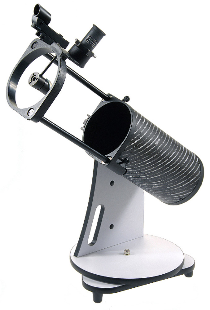
I am Software Developer and plan on using Arduino to make telescope tracking. It is light dobsonian type of telescope Image.
I am good with software development, but mechanics are not my good side.
I was planing to buy:
-GT2 Timing Belt 2mm teeth
-2x 20 Teeth Stepper Motor Timing Pulley Nodal diameter: 16mm
-2x Nema17 stepper motor with specs :
Step angle: 1.8°,Phases: 2, U:3.96V;I:0.9A;R: 4.4 ohm;Holding torque: 0.34 Nm;Axis diameter: 5mm
-Arduino DUE
-2xSome drivers( A4988 or recommendation?)
-Some power supply, maybe batteries for arduino and for motors
This is sketch of two "gears" that stepper will move
So, If I calculated properly(which might be very wrong) this NEMA17 should have more than enough torque to push "gears".
Are this A4988 precise enough and good for arduino. I would like to keep costs as low as possible, while using drivers that are safe and precise enough. 200 steps is more than enough, but maybe 1/4 wouldn't be bad to smooth things out.
Looks workable. Are you picking the DUE because there is telescope drive software that runs on it? I THINK there is a lot of Arduino UNO/MEGA software out there..
You may want to use the belt as a belt not a gear; easier to adjust, less tolerance needed.
Overall, think about 'backlash' compensation in software (AKA 'always approach a point from the same direction"). 3D printers using these belts/pulleys seem to have little backlash, but with your friction it may matter.
Yes I am picking duo since uno has lot of limitations for this project, as stated in this indestructible It will be controlled with Stelarium app and its telescope plugin, and Arduino will have to do conversion of Equatorial coordinates to AltAz coordinates every few milliseconds
I would like to use belt as gear because it will make least damage to telescope stand. I would use it as belt of bigger "gear". For smaller I can fit real gear since it is easy to disassemble and add additional parts.
I thought that for finding object big one will move about 90°(~125 teeth) in few minutes, so around 5-10rpm
and for tracking will move very very slowly, big gear will move 90°(~125 teeth) in 6 hours and small one even less when tracking
I am Software Developer and plan on using Arduino to make telescope tracking. It is light dobsonian type of telescope Image.
I am good with software development, but mechanics are not my good side.
I was planing to buy:
-GT2 Timing Belt 2mm teeth
-2x 20 Teeth Stepper Motor Timing Pulley Nodal diameter: 16mm
-2x Nema17 stepper motor with specs :
Step angle: 1.8°,Phases: 2, U:3.96V;I:0.9A;R: 4.4 ohm;Holding torque: 0.34 Nm;Axis diameter: 5mm
-Arduino DUE
-2xSome drivers( A4988 or recommendation?)
-Some power supply, maybe batteries for arduino and for motors
This is sketch of two "gears" that stepper will move
So, If I calculated properly(which might be very wrong) this NEMA17 should have more than enough torque to push "gears".
Are this A4988 precise enough and good for arduino. I would like to keep costs as low as possible, while using drivers that are safe and precise enough. 200 steps is more than enough, but maybe 1/4 wouldn't be bad to smooth things out.
Thanks guys in advance!
You will need to use microstepping anyway, 1/16 or 1/32, unless you want bad noise, vibration and mis-stepping.
Holding torque is no use to you, you need to find the motor's torque/speed curve for the supply voltage in question to figure out if it has enough torque - give generous safety margin here, factor of 2 or 3, due to resonance issues and all the unknowns. I've no idea if that meter will work from the figures available.
Measure the actual torque needed through the belt drive, belts can add a lot of friction (use the most
flexible kinds of belt for precision work, not stiff thick ones).
Definitely do not want noise or vibration or especially mis stepping since that would mean recalibration
So I will get belts and gear first, and ask my cousin to borrow torque screwdriver, if I am not wrong he has one that goes from 0.1nm to 3nm that should be more than enough to measure required force
Vulisha:
Definitely do not want noise or vibration or especially mis stepping since that would mean recalibration
So I will get belts and gear first, and ask my cousin to borrow torque screwdriver, if I am not wrong he has one that goes from 0.1nm to 3nm that should be more than enough to measure required force
Torque is easy to measure, just measure tangential force on a level and the off-axis distance of that point,
multiply together.
Again the same,
If I don't comment out ENA, motor won't work (no sound of any kind from motor), when I comment it out, it is by default, I can hear current. but it always spins in one direction. When I swap red and green wires it goes opposite direction (B+ and B-)
int PUL = 10; //define Pulse pin
int DIR = 9; //define Direction pin
//int ENA = 8; //define Enable Pin
void setup() {
  pinMode (PUL, OUTPUT);
  pinMode (DIR, OUTPUT);
  //pinMode (ENA, OUTPUT);


  for (int i = 0; i < 6400; i++)
  {
    digitalWrite(DIR, LOW);
    //digitalWrite(ENA, HIGH);
    digitalWrite(PUL, HIGH);
    delayMicroseconds(50);
    digitalWrite(PUL, LOW);
    delay(50);
  }

}

void loop() {
}
That's what I would expect as it is the way I wrote the program. What happens if you change the line
digitalWrite(DIR, LOW);
to
digitalWrite(DIR, HIGH);
If that does not solve the problem then make a simple pencil drawing showing clearly how you have everything connected and post a photo of the drawing. See this Simple Image Guide
By the way the ENA pin may need to be LOW to make the motor work. However with many stepper drivers it only needs to be connected if you wish to be able to disable the stepper driver with your program.
I did change DIR from LOW to HIGH but it spun in same direction.
So I decided to risk a little bit and Changed configuration completely to Catode, so connected all minus poles to GND and left all other on PWM, and it didn't work as well, and then I connected to DIR ENA and PUL to DIGITAL 5V part, and it worked without ENA, and then I came hare to see ENA LOW and it worked ;D
I do not have any other arduino, but I think this digital pins work with 5V(I think I measured 4.5 V but will recheck with multimeter later today) since it is printed on top of the board
I was following this guide:
So I connected driver to PWM at first, and later to digital then it started to work
Arduino Due has separate PWM pins and DIGITAL pins. At first I connected driver to PWM because in tutorial above they are connected to PWM and it didn't work. As soon as I connected them to DIGITAL pins it worked.
Voltage on DIGITAL pins measured with multimeter is 3.2 so it looks like TB6600 works with 3.3 as well, although it is cheap and slow multimeter maybe it doesn't meassure full voltage so this should be taken with reservation.


