Wow, what an incredible response!
I wrote the post just before going to bed, so as not be kept awake thinking about the project.  Thanks for the input BTW!
It's a bit chaotic trying to reply to each commenter, since there are so many. Instead I'll just try to answer the following:
- General description of project philosophy, as this influences the design
- Motorized valve specifications
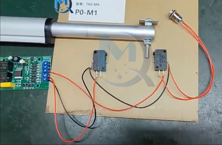
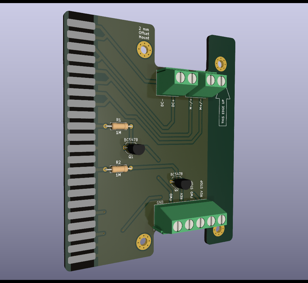
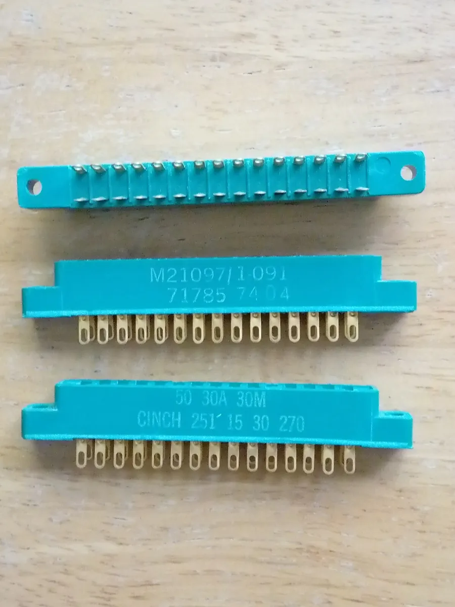
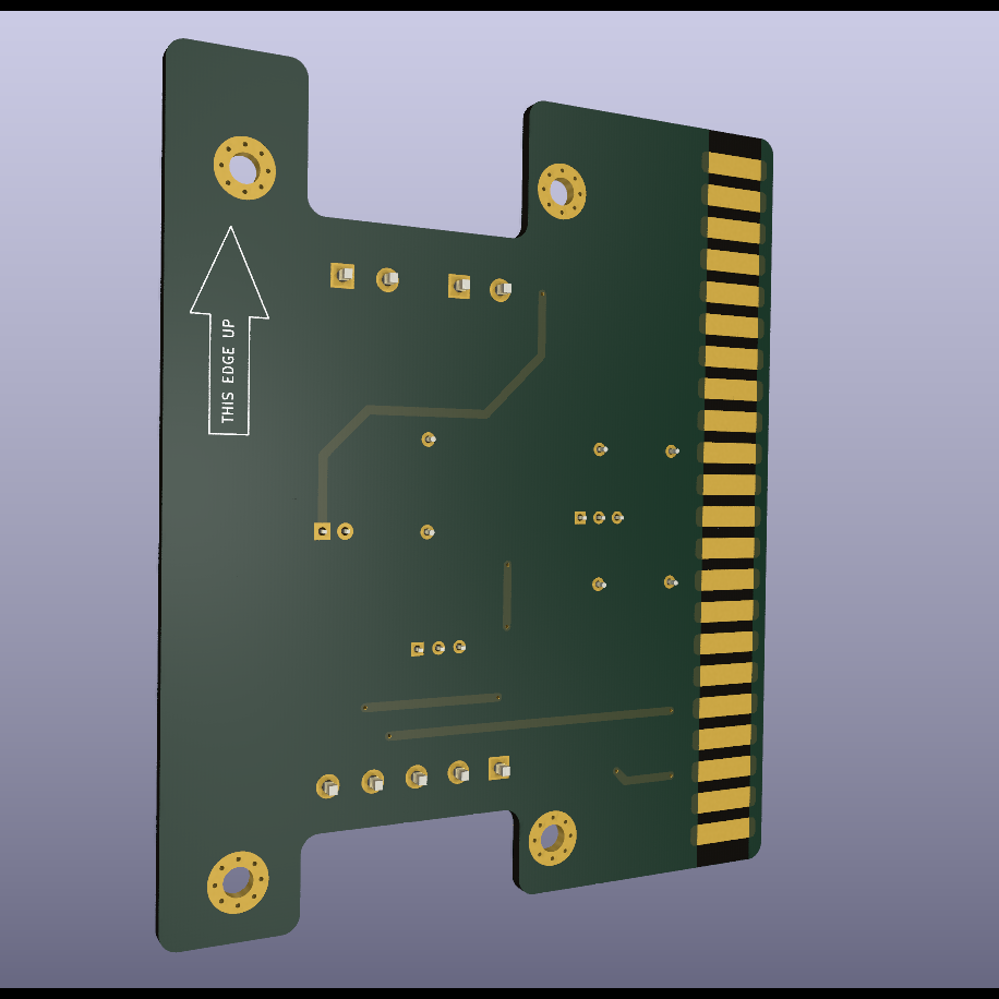
- Module/board specification
Description of project and design philosophy
My general design philosophy is designing as simple as possible. I was thinking of buying cheap parts, i.e. via Aliexpress, and have a stock of reserve/back up components in storage. If a motorized valve breaks, or if a circuit stops working, I should be able to change it out effortlessly.
There are two reasons for dividing up in more zones with individuel valve control:
- Plots and areas within plots will be divided up depending on water requirement, i.e. smaller pots require less water, some seedlings require less moist soil, some seedlings have foliage that both blocks out rain and perspirates more thus requiring more water.
- While drip nozzles don't steal a lot of water and pressure, if you have 40-50 points on one line, you will have a large pressure drop and lower pressure towards the end. Thus there is a limit to how many watering points I can have on each line.
I have around 500 seedlings at the moment, so I will probably require at least 20 valves.
Also, there was a question as to if I need several lines to be active at a time: No, I plan on activating and watering one zone at a time. This is regarding the water pressure consideration I mentioned earlier.
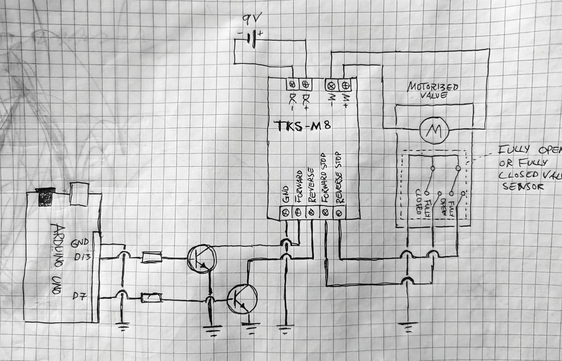
Motorized valve specifications
I plan on using ** this ** or equivalent motorized valve.
It has this schematic:

And these specifications:
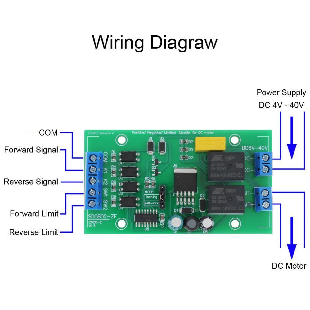
Module/board specifications
The card I was looking at, was the SD0802-ZF. It has a jumper which can be moved to select either Self-Locking mode or a Jog mode. As the switches K1 or K2 are pressed, the polaritiy locks in respectively forward or backward direction. Moving the jumper, and K1 or K2 will lead to energized output in forward or backward direction only as long as the buttons are pressed.
You can se the item HERE.
Concluding remarks
I'm open to alternatives and different solution to the module shown. However, I'm sceptical to using wifi or other wireless solutions to control the units directly, so a totally wired solution is preferrable. I was thinking of using 12V for my system, though up to 24V is an alternative.
Again, thanks for input and responses!