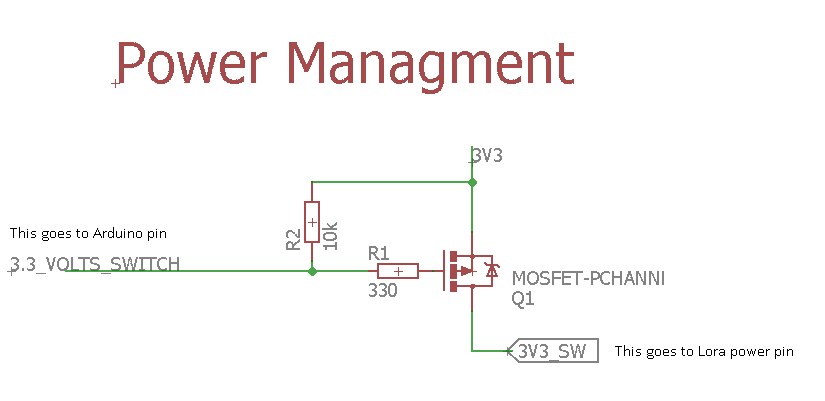
I have an Arduino Pro Mini. I use one of it's pins to power on (and off) a Lora RA-01 module using a mosfet (FQP27P06).
Arduino is powered with 3.6V (ok, I know it's more than it should, never mind this) but when the mosfet is switched on it outputs 2.6V instead of 3.6V. I suppose it doesn't open fully with 3.6V.
What can I do to correct this? Any ideas?
(in the attachment you 'll see 3.3V, in fact it's 3.6V, from a battery)
I like the IRF3708PBF - though it's overkill for that load. Great part to have on hand as it allows switching relatively large loads with only 3.3v on the gate.
I recently had to pick a p-channel mosfet for controlling a common anode for a bunch of LEDs. I went with the AO3401A. Small package (SOT-23), low gate voltage and very low RDSon.
Just make sure you get genuine ones. Counterfeits have a much higher RDSon, so watch out for cheap Ebay listings!
I don't know how much current you're switching, but the LP0701 is a pretty capable P-channel that comes in a TO-92 package.
And I'm not sure why the gate resistor is there. It just puts the gate in the middle of a divider, and doesn't let it go all the way to ground. Or changing the pull-up resistor to 100K would also help.
ShermanP:
I don't know how much current you're switching, but the LP0701 is a pretty capable P-channel that comes in a TO-92 package.
And I'm not sure why the gate resistor is there. It just puts the gate in the middle of a divider, and doesn't let it go all the way to ground. Or changing the pull-up resistor to 100K would also help.
Feel free to post a better way (with schematic if possible) to do this switching, even with an N-Channel MOSFET.
This is what I found on the internet.
Maybe I should do it like this?: (taken from here)
Or this (from the same topic):
And one that uses a very similar MOSFET to mine: (from here)
Having to much capacitance on the switched VCC can trigger a brownout of the Pro Mini especially as a lot of them have the fuses set for a 2.7V brownout.
However since the LoRa devices consume less than 0.1uA when in sleep (easy to do) you normally dont need to bother with switching.
Yes, I was thinking of the switch with a mosfet in case I put more things than just o Lora module.
If I don't add anything other than Lora, I will remove the mosfet.
I think all you really need to do is use one of the recommended mosfets with a low gate-source threshhold so it will turn on fully at 3V. Any of them should handle 120ma.
Not being professionally trained, I just don't understand why the Arduino can't drive the gate directly, with no inline resistor. But I see it a lot, so I'm sure there's a good reason. Maybe if there's enough capacitance on the gate it would cause problems for the Arduino (too much current), but it's hard to see how it could be that much. The resistor does slow down the transition, and modestly reduces the gate-source differential, so in theory the mosfet doesn't turn on quite as fully as with no resistor. Anyway, I'll have to read up on all that.
ShermanP:
The resistor does slow down the transition
Which in turn reduces the spikes on the power rail being switched.
If the device being switched have significant capacitance the spikes generated can be enough to trigger brownout in the processor. Common issue when switching the power on GPSs for instance.
Yes, I've been reading up on gate resistors, and I see why they are used. Apparently they also prevent ringing, which could prevent the mosfet from turning off.
But, can we at least move the resistor over next to the gate and get rid of the divider situation? See pic.
Well, the OP's schematic showed the gate at the midpoint of a resistor divider which limited the G/S differential to 3.2V when the Arduino output goes low. And I'm just asking if it wouldn't be better as a general rule to move the gate resistor over so the differential can go to the full 3.3V. That's a small difference, but why not do it the "right" way. The only other difference is that the pullup resistor is effectively changed from 10K to 10.33K. I don't know if either version works on his circuit.
Put another way, is there a reason why you would want to use the resistor divider configuration?
Gate pulldown should be connected to the arduino-side of thed gate series resistor, not the mosfet side where it will form a divider. You can very often get away with it the other way around, bug its not best practice.