I have a laser cutter and want to add a sensor to the Z axis to determine the zero position of the material that I am cutting.
I can't use a switch (that would be too easy) as the switch would have to be clear of the work piece.
I really need a digital signal 0 and 1 that is activated at the same distance each time the Z axis moves toward the work material. I can the use this with offsets and macros to set the Z position as required for the various materials and thicknesses.
A5 on the Uno is the probe pin. and I have tested the theory on a dummy machine (just a Uno connected to computer) and it works fine with LaserGRBL, I now have to find a suitable sensor to do the job.
Any ideas please?
Wish I could see your actual setup but as one suggestion you may be able to use a Linear Voltage Displacement Transducer. How are you measuring the X and Y axis? Activation of a digital 1 or 0 is just a matter of code.
Ron
I have limit switches on both ends of the X and Y and a single limit switch at the top of the Z axis.
I have modified GRBL config.h lines 129 and 155 to suit my system.
I want to add a probing sensor of a suitable kind to the Z axis, everything else is working fine.
At present I am homing the system, and using some macros to send the Z down to the right position for various thicknesses of material.
An example is for 3mm thick material and that works very well each time.
G0 Z-101, go down 101mm after homing for 3mm thick material
G92 Z0, set Z axis to zero
The problem with using this method is that if I need to take the laser module off the machine for cleaning or adjustment, I would have to recalibrate all settings again in the macros as it would be pretty hard to get the exact placement again when putting the laser module back in place. Having a sensor that is attached to the laser module would overcome this problem.
But then you would also have to calibrate the sensor, because it will move with the laser module.
My 3D printer has a Z probe that is used to make sure the nozzle is the correct distance from the build plate. My suggestion is to look at a few machines and see if the probe makes sense. On my machine it looks like THIS
1 Like
Two ways machinists solve this are to:
-
temporarily place a known-height switch on the workpiece and touch off with the tool
-
temporarily place an inert known height block on the work piece and touch off a switch on the toolholder.
The 3d printing probes (BL-Touch, CR-Touch) use an retractable probe that triggers a switch on the extruder.
Of course because the laser module is on the Z axis that has to move to do the measurement. Only one calibration needed, that is distance from the laser module to the material surface.
Yes I was thinking about what sensors are used for 3D printers, some are using non contact types I am sure, but I need to find which they are.
This looks very promising. After looking at the website, I was unable to find any info on using it with a Uno board, so I will do a bit more research on that. It seems to be the best idea so far.
Yes that does look promising. Not enough info on their website as it is just a replacement part for their machines.
It's two pins -- one Servo.h-controlled pin to control the probe location, and one pin to read the probe pulse. From the BL touch page:

You'd send a myservo.write(10), then slowly move towards your bed while monitoring for a 10ms pulse on the sense pin and do a meservo.write(90) to retract.
Look at about 1:30 in their sales youtube video where they parallel it with with a servo.
Dave I might need some help with this. The sensor looks ideal for what I want to do, but I am using a Uno board and GRBL 1.1h,
The only pin I have available is not a PWM pin, so maybe there will need to be some pin reassignments, which I am not familiar with doing.
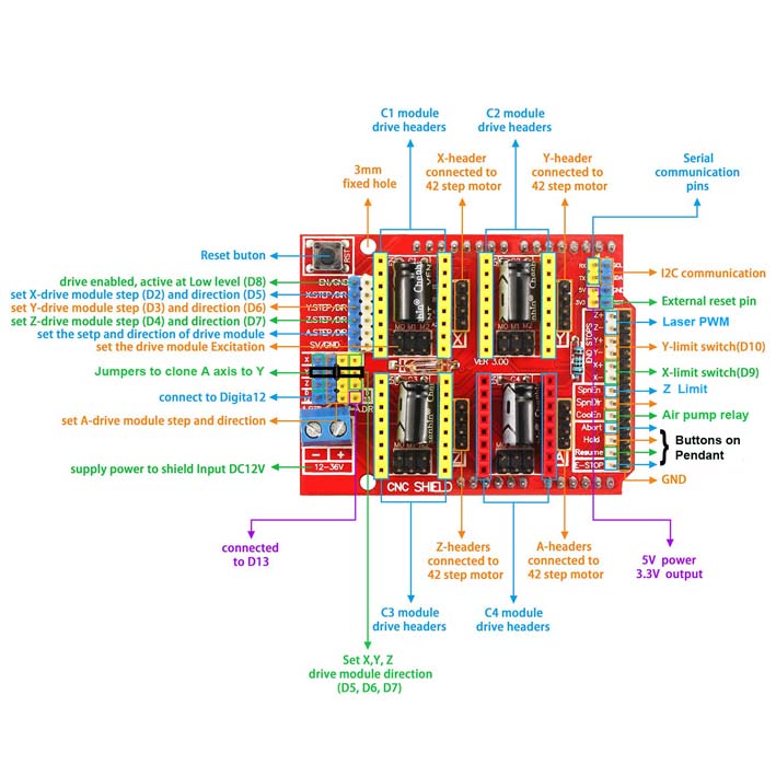
My wiring for this machine is shown below;
I found this while searching, but I don't have any experience doing it and am not sure of it.
If the reason you want to remap the pins is because some code you use assumes PWM on the wrong pins, then simply create a method transform() that takes in a pin number and maps it to another (use a switch case statement). Then, replace (most IDEs have a find/replace function) all the digital/analog read/write methods with a new set of functions, for example:
void digitalWrite2(int pin, int val){
 digitalWrite(transform(pin),val);
}
I'm sorry, I had your question confused with something else. Interfacing a BL-touch to grbl is not straightforward. I did see hints that someone built an interface between the two with an ATTiny:
...but the project seems deleted. I did find this document:
Why do you ask that?
A servo signal does not require a PWM pin.
Leo..
Oh! I was not aware of that. The only pin I have left without making any changes is SpinDir but I think it may also be used in conjunction with another pin
No experience with that shield. Have to dig into the schematic and pinout.
There could be an analogue pin free for that servo signal.
Leo..

Uhh, no. The question was about which pins the shield uses.
No experience, but Google says that with a CNC shield pins A4, A5 are free to use.
Note that there is no PWM functionality on pin 8,9 with the servo library.
Leo..
A5 is the probe pin
8 and 9 I am using already for other things