Hi! Before anything, I know the ABSOLUTE max supplied current of any pin is 40ma, but I did something a lot wierder, and that should (as of how I see it) burned the Arduino to ashes!!
So what I did was:
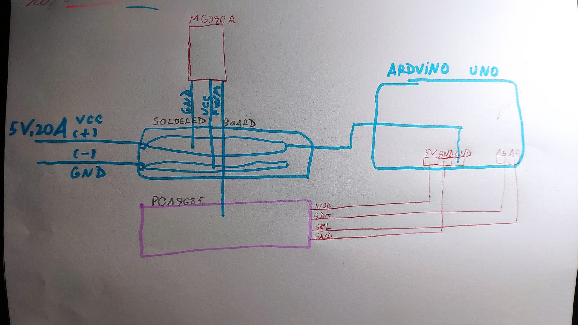
Got a 5.5V , 20A power supply, a prototyping board, 5 MG996R servos, 5 X 1KG of Flour and a PCA9685. Here's the schematic:
I soldered 2 parallel lines of (-) and (+) from the power supply on fhe prototyping board, (Check the attatched photo)
then wired all 5 servos in parallel so that the VCC was to (+) and GND to (-)
Wired every PWM cable to the PCA, which was connected to the Arduino
Connected a (-) wire from the Servo line DIRECTLY to the Arduino GND (from what I know, all components must have a common ground)
Attatched 1 KG weight of flour to each servo to make them lift it up
Then plugged the arduino in the laptop, and it worked!!
But how come it didn't burn anything?? EVERY servo consumes 2.1A at stall current, which means max stress or having a weight, that means 2.1A X 5 = 10.5A flowing to the Arduino through the GND pin?!?! That's a much higher amount than the 200mA that it's rated for, and it somehow survived!
I cannot see from your photos where any of the current is flowing, but I doubt it's going anywhere near the Uno. Please post a schematic, which is a drawing not a list of connections. Hand drawn and photographed is fine.
The servo has its own built-in motor controller. The PWM signal does not provide the power to the motor so the Arduino isn't providing all that current through its pins
Yeah but, since they all have a common ground (check the drawn circuit above), doesn't that mean the current is flowing THROUGH the Arduino as well? The 5V, 20A
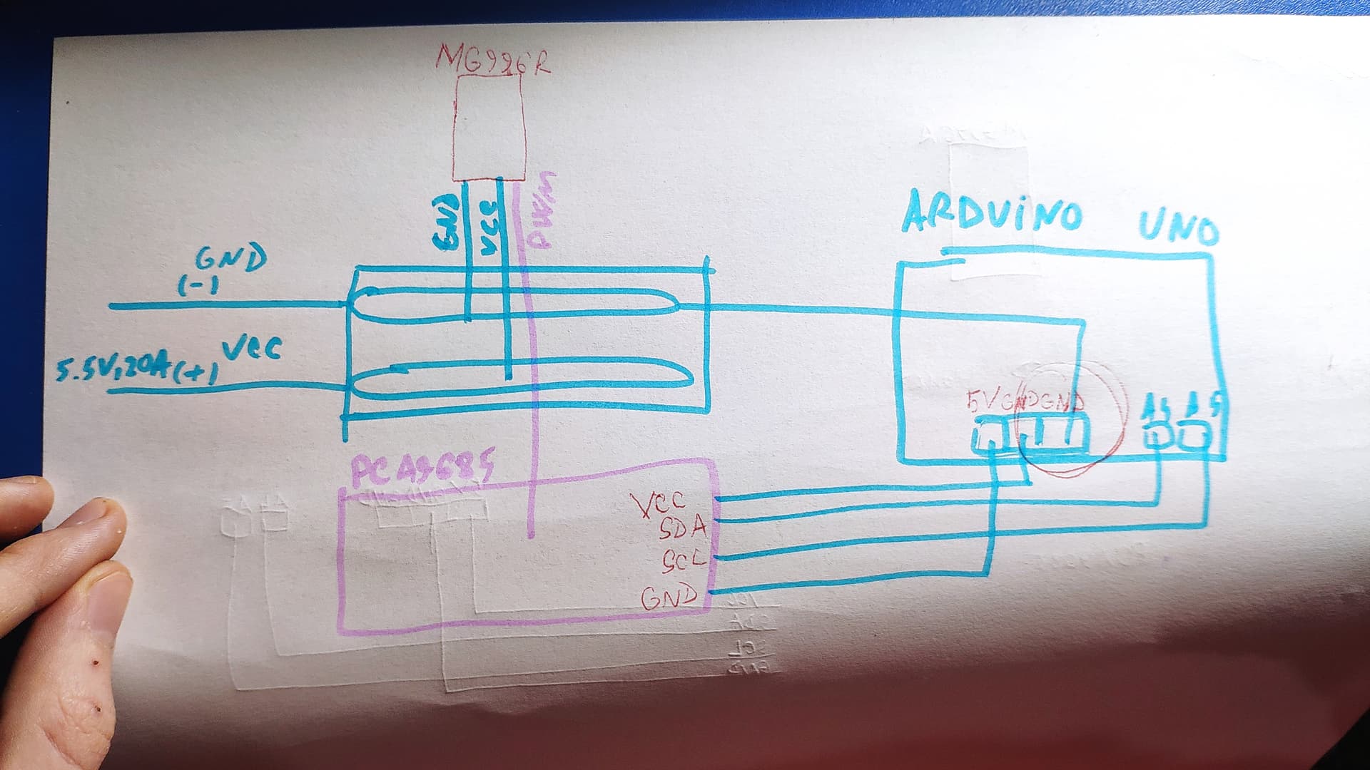
Note: they were supposed to be 5.5V in the photo but nevermind
But isn't the GND of the prototyping board connected to the GND of the UNO port? Doesn't that make the current flow through the UNO as well? Like in this scheme, where I made the circle (I made it again)
Oh... So there's no current flowing through the Arduino at all then, since it doesn't need it since it already has a power supply (the laptop) I guess? And those 2.1 X 5= 10.5 A are not flowing to its GND, just through the servos ?
They need that common connection, but that doesn't necessarily mean the high current will get to all components if I got this right?
There's no high current to the servos through the Arduino.
No, because the path for the current to the servos doesn't go near the Arduino.
I refer you to my reply #8, I'm still waiting for you to show on your schematic the path you think the current to the servos takes through the Arduino.
What I'm wondering is, and yeah I know the Arduino is an extra resistance for the current, is why didn't it take it? Every servo takes 2.1A, as much as it needs to operate. The arduino was plugged in the laptop so it didn't need to draw any current from the prototyping board?
Come to think of it, to be able to draw any current from the circuit, it would've needed a connection to the (+) as well. In which case that is where I think it would have burned, since it was connected to the 10.5 A tin line? Or would it have just drawn the amps it needed and stayed safe?
The 200mA limit is the total for the chip, (from the ATmega datasheet) not the PC board. That's the total current powering the chip plus any current into or out-of the output pins.
It's (probably) not going to die if you push that to 201 or 210mA but you can't complain if it does.
The current limit through the voltage regulator is more difficult to nail-down. The heat generated is a combination of the current-through, and the voltage dropped-across the regulator. And the actual temperature before it burns-up (or goes-into protective shut-down) also depends on ambient temperature.
I'm not sure how much the power & ground traces on the PCB can tolerate but I'd guess 1A is "pushing it".
That exact GND connection from the prototyping board to the UNO. I wonder though... Since it would have needed a (+) connection to the board as well to be able to draw current?
But yeah, that's the wire I thought is bringing the current