i have 1 that works, just these dont work and keep returning 0;
im testing this with a simple Serial.println(digitalRead(pinnumber))
i have 1 that works, just these dont work and keep returning 0;
We can't see your code.
We can't see your schematic
void setup() {
Serial.begin(9600);
pinMode(2, OUTPUT);
pinMode(8, OUTPUT);
pinMode(9, OUTPUT);
pinMode(11, OUTPUT);
pinMode(12, OUTPUT);
pinMode(13, OUTPUT);
   pinMode(6,INPUT);
   pinMode(4,INPUT);
      pinMode(5,INPUT);
            pinMode(7,INPUT);

}
int ingedrukt = 0;
int westKnopPin = 4;  //doesnt exist
int oostKnopPin = 5; //no
int  noordKnopPin= 7;//yes
int zuidKnopPin = 6; //no
void loop() {
    digitalWrite(2, HIGH);
    digitalWrite(8, HIGH);
    digitalWrite(9, HIGH);
    digitalWrite(11, HIGH);
    digitalWrite(12, HIGH);
    digitalWrite(13, HIGH);
//   ingedrukt = digitalRead(zuidKnopPin);
//   Serial.print(" PIN ZUID :  ");
// Serial.println(digitalRead(zuidKnopPin));
//   Serial.print(" PIN NOORD : " + digitalRead(noordKnopPin));
//   Serial.println(digitalRead(noordKnopPin));
//   Serial.print(" PIN WEST : ");
// Serial.println(digitalRead(westKnopPin));
//   Serial.println(" PIN OOST : ");
//   Serial.prin(digitalRead(oostKnopPin));
delay(20);
Serial.println(digitalRead(4));
  Serial.println("--------------------------------------------------------");
  if(ingedrukt = 1){
        digitalWrite(2, HIGH);
  }
        digitalWrite(2, HIGH);

}


should i make schematic of the whole board or just the relevant buttons?
Did you mean "=="?
Not that it makes any difference + both branches are the same.
Can you use the auto format tool?
yh my bad, im testing the input with the serial.println so i dont think its a software problem.
oke let me use the auto format
void setup() {
  Serial.begin(9600);
  pinMode(2, OUTPUT);
  pinMode(8, OUTPUT);
  pinMode(9, OUTPUT);
  pinMode(11, OUTPUT);
  pinMode(12, OUTPUT);
  pinMode(13, OUTPUT);
  pinMode(6, INPUT);
  pinMode(4, INPUT);
  pinMode(5, INPUT);
  pinMode(7, INPUT);
}
int ingedrukt = 0;
int westKnopPin = 4;   //doesnt exist
int oostKnopPin = 5;   //no
int noordKnopPin = 7;  //yes
int zuidKnopPin = 6;   //no
void loop() {
  digitalWrite(2, HIGH);
  digitalWrite(8, HIGH);
  digitalWrite(9, HIGH);
  digitalWrite(11, HIGH);
  digitalWrite(12, HIGH);
  digitalWrite(13, HIGH);
  //   ingedrukt = digitalRead(zuidKnopPin);
  //   Serial.print(" PIN ZUID :  ");
  // Serial.println(digitalRead(zuidKnopPin));
  //   Serial.print(" PIN NOORD : " + digitalRead(noordKnopPin));
  //   Serial.println(digitalRead(noordKnopPin));
  //   Serial.print(" PIN WEST : ");
  // Serial.println(digitalRead(westKnopPin));
  //   Serial.println(" PIN OOST : ");
  //   Serial.prin(digitalRead(oostKnopPin));
  delay(20);
  Serial.println(digitalRead(4));
  Serial.println("--------------------------------------------------------");
  if (ingedrukt == 1) {
    digitalWrite(2, HIGH);
  }
  digitalWrite(2, HIGH);
}
Hi!
Here goes my 5 cents:
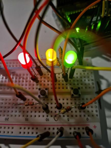
on your first topic (https://forum.arduino.cc/t/why-does-this-always-return-1/1127539) you´ve received a tip to connect buttons using the pins on opposite corners. In the picture of post #1 this advice seems to have been forgotten.
A nice way to connect buttons is one side to a pin configured as INPUT_PULLUP and the other side to GND. So pin will read HIGH until you push the button. Then it will read LOW.

Looks like one would expect the output in the serial monitor to normally be:
0
--------------------------------------------------------
0
--------------------------------------------------------
0
--------------------------------------------------------
0
--------------------------------------------------------
0
--------------------------------------------------------
And when you press the button:
1
--------------------------------------------------------
1
--------------------------------------------------------
1
--------------------------------------------------------
1
--------------------------------------------------------
1
--------------------------------------------------------
What do you get?
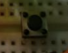
The opposite corners advice is good advice. The buttons in the pic are smaller than are shown in diagram. If you inserted and connected these buttons with a 90° turn, instead of the pull-down pulling pin 4 to ground through the internal connection, the internal connection would connect the +5 to the pulldown resistor and pin4 would be floating or connected to +5, giving unreliable results.
sorry for the late response i was sleeping.looking back i see the colours are a little messed up in the first pic but its the same as the schematic.
2. the input pullup and removing the 5v didnt help. now it just always returns 1
3. thanks ill take a look
sorry for the late response i was sleeping,
I just always get a 0.
If you always get a zero, that means that nothing is pulling the pin away from ground. Any 5V at the switch is not making it through the switch to the pin. Do you have a meter or probe that can measure the voltage going into one part of the switch and out of the other parts of the switch?
i now have the wires on the same side and it worked, thanks for the help
Great!
Please post a pic of the changed and working connections for posterity.
This topic was automatically closed 180 days after the last reply. New replies are no longer allowed.