I have searched the to my ability and i am unable to find a answer to my question , I recently brought a Arduino starter kit , inside the project book of the starter kit ( the second project) you put a resistor back to ground which confuses me, why back to ground? wouldn't you want it to the led to stop it from over-heating? In the last circuit there is no resistor back to ground, so why now?
Show us a good schematic of your proposed circuit.
Show us a good image of your ‘actual’ wiring.
Give links to components.
Welcome to the forum
Is the resistor that you are referring to is being used to keep the switch input pin LOW until the button is pressed to take it HIGH ? If so, the reason it is there is to keep the input pin in a known state at all times
Please read the how to use the forum post. Your post includes little information that we can use to help you.
There are any number of reasons to "put a resistor back to ground".
Post a link to the project book. Tell us which exact project. if necessary, point out the resistor that you are questioning.

are you talking about the 10KΩ resistor?
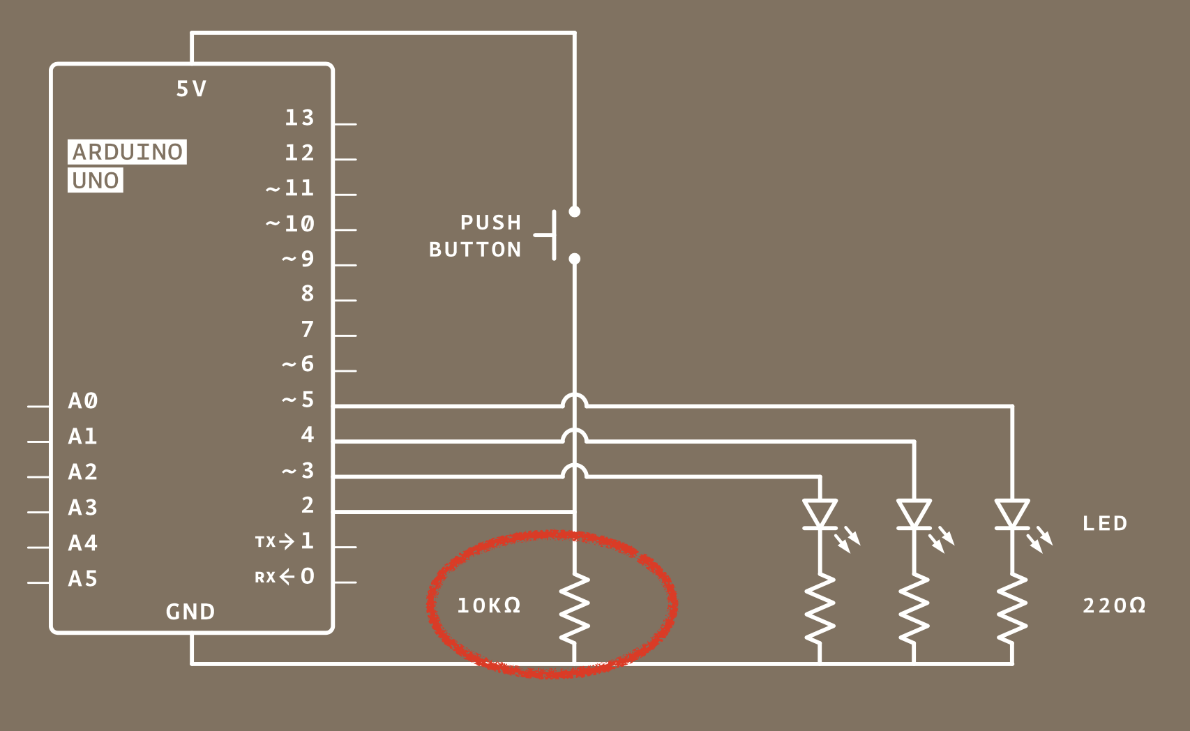
It's a pull down resistor for pin 2. When the switch is not pressed, pin 2 is connected to ground (through that resistor) and thus reads a LOW.
if you did not have it, when you push the switch the 5V would be directly connected to GND and this is the definition of a short circuit ➜ don't try it...
with 10KΩ, the current that will go through the resistor (I = U / R) is 5V / 10000 ➜ 0,5mA. It won't boil the ocean.
FYI

Your switch circuit is the same as S1 and R4 in the above schematic.
This kind of connection obviously works but there is an inherent danger in using that interconnection, see the yellow highlights.
After you are finished learning that section in your book, in future projects, we suggest you use the circuit S3 in the schematic above.
In your example a S1 closed switch is detected as a HIGH level on the input pin.
In the S3 connection, we look for a LOW for a switch closed on the input pin.
The switch S3 connection relies on an internal (programmable) input pull up resistor by this line of code:
//in the schematic above

Your S1 connection uses:
pinMode(10, INPUT);
. . .
The S3 connection uses:
pinMode(3, INPUT_PULLUP); //turn on the internal input pullup resistor
FYI
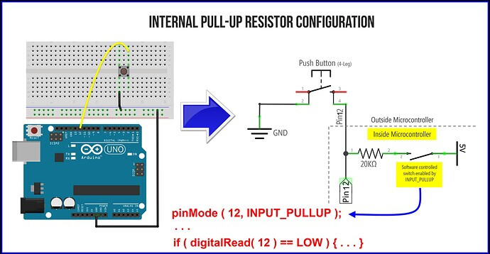
The MCU (AtMega328) has built in pullup resistors for just this purpose,
(eliminate external resistors). The picture shows the LEDs connected backwards, the longer lead is the anode (positive) connection.
Looks to me like the author of that book was an amateur "programmer" with little knowledge of microcontrollers or electronic components.
So they simply would not work at all. ![]()
From where do you get such awful "project books" with "starter kits"? ![]()
yeah, that's weird. In the PDF I found on line the anode/cathode are properly connected

not sure if this is that tutorial though
no no , i understand the pull down resistor just i do not understand why we are running 5volts through the LEDS then putting a resistor behind the cathode.
yeah, this one. On the negative rail they put resistors underneath the cathode , wouldnt 5 volts through the LED over heat it? Then putting the 5 volts through ground to return to the circuit. That is what I do not understand
It is to limit the current through the LED. It does not matter where it is in the circuit as long as the current to the LED goes through it
I think you are confusing voltage with current.
The resistor and the LED are in series so the same current flows through both of them - the amount of current is determined by their collective resistance, and the voltage (in this case 5v) across them. The resistor is required to stop too much current flowing through the LED and damaging it.
Have a look at some basic electronics tutorials for more detail.
but the current is going through the positive rail, not grnd rail? surely the current would pass through the LED then through the resistor?
The LED and the resistor are in series so, as has been pointed out, the same current flows through both of them on its journey between GND and 5V so it does not matter in which order they are placed
5V - LED - resistor - GND
or
5V - resistor - LED - GND
The same current flows
I did not see the series resistor reply before i saw your , thank you anyway though
Indeed it does, but in an electrical circuit, the same current flows through all parts of a closed loop. If it is not a closed loop, no current flows. That is what an electrical circuit means. ![]()
This topic was automatically closed 180 days after the last reply. New replies are no longer allowed.