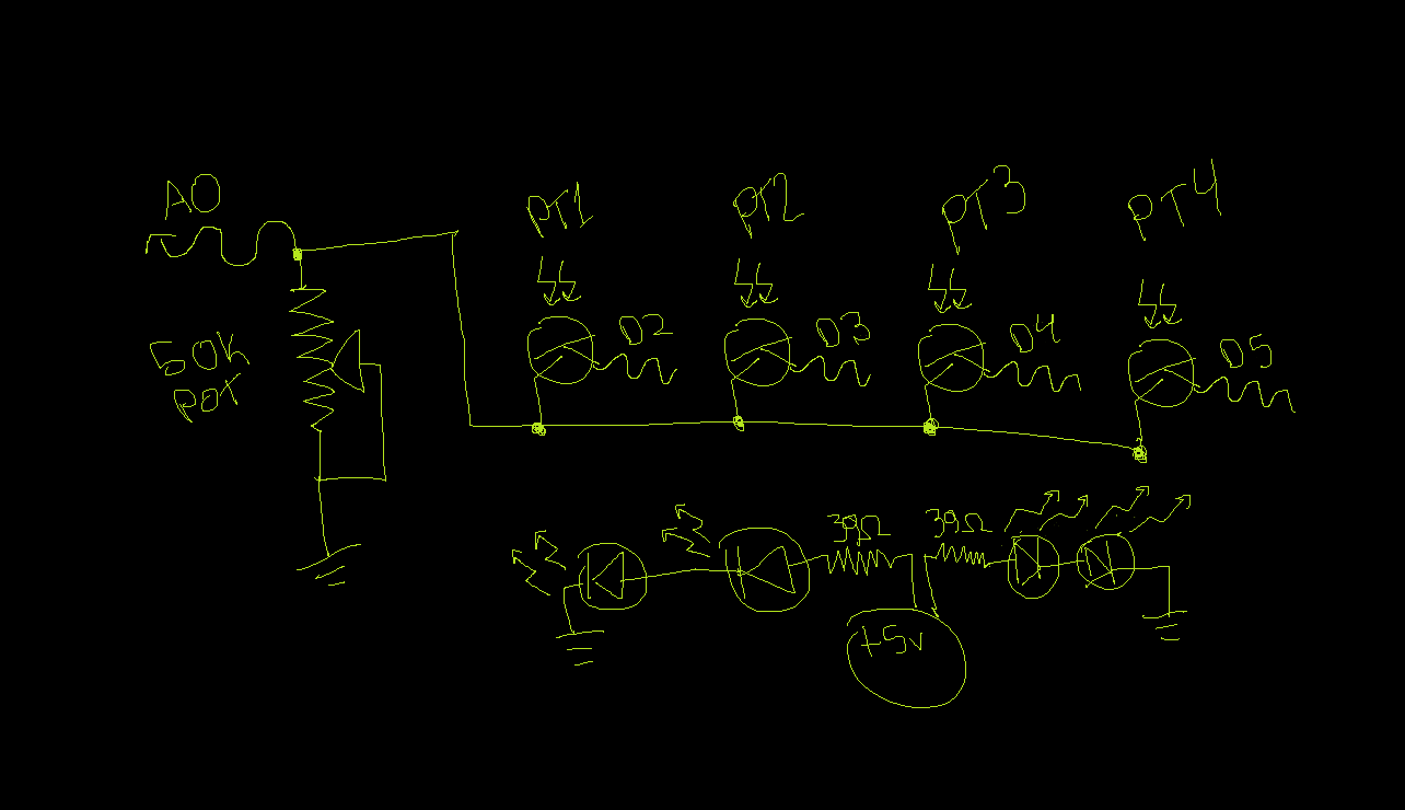
I have a 4x1 matrix of infrared photo-transistors because i want to use 4 digital outs and one analog in to control it. So when i write one HIGH, read it, the write it LOW, it behaves as if it were alone an none of the other PTs where even there. But if I write it HIGH and leave it HIGH, as you might expect, the signal from that PT is also read as the signal from all the other PTs. But the weird thing is, when i do that, instead of getting a value of about 280, it goes down to 4. why would it go down so much? It's just reading the same thing as before only 4 times more frequently. And if i do it the right way, turn it off before moving on, then speed it up 4 times faster, it does exactly what it did before it was sped up. So i'm pretty sure speed has nothing to do with it. When I try to include a second one with the first, It reads zero like the others and the first one is unaffected. Same when i include all 4. The weirdest part is, the other 3 respond to change in light instead of the amount of light. Why would one be normal, and all of them normal when i switch them one by one myself, but when the computer does the changing, no matter how slow or fast, 3 lights respond only to change while the first is normal? Attached is a crude circuit diagram i drew in paint.
Here's my code:
int val1;
int val2;
int val3;
int val4;
int PT1 = 2;
int PT2 = 3;
int PT3 = 4;
int PT4 = 5;
int t = 1;
void setup()
{
  Serial.begin(9600);
  pinMode(0, INPUT);
  pinMode(PT1, OUTPUT);
  pinMode(PT2, OUTPUT);
  pinMode(PT3, OUTPUT);
  pinMode(PT4, OUTPUT);
}

void loop()
{
  digitalWrite(PT1, HIGH);  // give power to the first PT
  val1 = analogRead(0);     // check the voltage at the first PT
  delay(t);
  digitalWrite(PT1, LOW);   // cut power to the first PT
  digitalWrite(PT2, HIGH);  // give power to the second PT
  val2 = analogRead(0);     // read
  delay(t);
  digitalWrite(PT2, LOW);   // repeat
  digitalWrite(PT3, HIGH);
  val3 = analogRead(0);
  delay(t);
  digitalWrite(PT3, LOW);
  digitalWrite(PT4, HIGH);
  val4 = analogRead(0);
  delay(t);
  digitalWrite(PT4, LOW);
  Serial.print(val1,DEC);
  Serial.print(",  ");
  Serial.print(val2,DEC);
  Serial.print(",  ");
  Serial.print(val3,DEC);
  Serial.print(",  ");
  Serial.println(val4,DEC);
}
It works if i write the pins low before the delay and then slow down the whole thing an absurd amount
New Code:
int val1;
int val2;
int val3;
int val4;
int PT1 = 2;
int PT2 = 3;
int PT3 = 4;
int PT4 = 5;
int t = 50;
void setup()
{
  Serial.begin(9600);
  pinMode(0, INPUT);
  pinMode(PT1, OUTPUT);
  pinMode(PT2, OUTPUT);
  pinMode(PT3, OUTPUT);
  pinMode(PT4, OUTPUT);
}

void loop()
{
  digitalWrite(PT1, HIGH);  // give power to the first PT
  val1 = analogRead(0);     // check the voltage at the first PT
  digitalWrite(PT1, LOW);   // cut power to the first PT
  delay(t);                 // wait to let it turn off (port commands could fix this)
  digitalWrite(PT2, HIGH);  // give power to the second PT
  val2 = analogRead(0);     // read
  digitalWrite(PT2, LOW);   // repeat
  delay(t);
  digitalWrite(PT3, HIGH);
  val3 = analogRead(0);
  digitalWrite(PT3, LOW);
  delay(t);
  digitalWrite(PT4, HIGH);
  val4 = analogRead(0);
  digitalWrite(PT4, LOW);
  delay(t);
  Serial.print(val1,DEC);
  Serial.print(",  ");
  Serial.print(val2,DEC);
  Serial.print(",  ");
  Serial.print(val3,DEC);
  Serial.print(",  ");
  Serial.println(val4,DEC);
}
Smaller values on the others are slightly increasing values of the first. The faster i make it go, the second and fourth drop to lower values. then the third drops to 0 and the fourth goes up a tiny bit. What is up with this weird behavior?
It is hard to see what you are trying to do. The schematic is not at all clear. You seem to have all the transistors in parallel and there is no multiplexing going on at all.
Grumpy_Mike:
It is hard to see what you are trying to do. The schematic is not at all clear. You seem to have all the transistors in parallel and there is no multiplexing going on at all.
What are you trying to acheave?
That's what the last guy thought. The ends of the phototransistors are connected to the arduino digital pins so that they dont have a signal unless they are written HIGH. because of this i can use on single analog input for four phototransistors. This isnt multiplexed to use the minimum number of pins. infact, it uses more pins than if it weren't multiplexed. It could be 2 analog inputs and 2 digital outputs, but i set it up as a 1 x 4 matrix, using 4 digital pins and only 1 analog input. The reason being, analog inputs are limited while digital outputs are plenty. obviously i have enough analog inputs now to do it the easy way, but i plan on scaling it up quite a bit to a 4 x 85 (because i would like at least a 25% duty cycle). which would use the same 4 digital outs but 85 analog ins. im basically just staring with one piece of the matrix before i make it bigger, to make sure i can do the code first. Im switching one PT on at a time so that i can read the signal from each individually with one input. So it is multiplexed but not quite effectively yet because there will be more to it later.
Well, for now im trying to achieve some knowledge about multiplexing. nothing really practical could ever come from something like this, but i hope to apply this learning experience to my current project. I just learned how to multiplex leds with the TLC5940 led driver and im going to make a 13 x 26 grid of RGB LEDs multiplexed like a 2 x 507 matrix with 32 TLC5940s to control it. I went with so many TLCs rather than a lower duty cycle because it needs to be bright enough to illuminate a square of frosted glass. It relates to this infrared phototransistor project because im going to give each LED in the 13 x 26 grid a phototransistor so that it can know when there is something on top of the glass and change the lights accordingly. Basically, it's going to be the coolest table ever. I could buy a crap load more TLC5940s and CD74HC4067es and forget about multiplexing all together, but that could add an extra $100 to the project and im already $100 over budget.
So basically, right now i need to know why speeding up the multiplexing would change the results of the read. seems like it could be a physics problem, or maybe the micro controller cant do what im telling it to without mixing it's results. Color mixing was a big issue i had to overcome when multiplexing LEDs with the TLC5940
What you are doing is not called multiplexing, is is known as a wired OR.
The problem with how you have wired it up is that it is all backwards. You need the emitters to go to ground and the collectors to go to the analogue input. Then you need a pull up resistor from the input to +5V.
If you search for
myzen sound square
The top hit should be my sound square project which has photo transistors wired like you should be doing.
It is acting odd the way you have wired it because of the speed that photo transistors can switch in that configuration. It would improve matters if you made your pull down resistor 5 to 10 K.
Grumpy_Mike:
What you are doing is not called multiplexing, is is known as a wired OR.
I did some research on the wired OR circuit. No, it's not a wired OR circuit. It is multiplexed. If it were a wired OR, the input would be shared. But it's switching so no two are sharing at one time. It's called ground multiplexing.
I still have no idea why it doesn't work the other way around. And now that I have it set up properly 3 of them are working, except the first of the 4 inexplicably get lower performance than the rest. It isn't the phototransistor itself, I've tried moving and replacing them. The results of some are changing to results of others still as well. And after some amount of time for no reason the second and third invert themselves. I have no idea how to explain this but it seems solutions are only temporary.
This might not be quite proper yet, but i spent a lot more time on this one and it's much more clear. Whatever you see, i mean exactly what is is in the link, it is exactly the same. The only difference is the resistor on the website is replaced by a potentiometer
The diagram on the website uses the symbol of an LED, but they are labeled as sensors
The more transistors you have in parallel the slower it will get due to the capacitance increasing.
What is the state of those Arduino pins when they are not selecting a transistor? Are they just an output with a zero? What they should be is to be set to an input, so they are in effect floating.
Oh, that capacitive thing explains it, i didnt think about that. I have those digital pins connected as outputs to write them high when im not reading a sensor, and low when i am, to provide a ground across the transistor while the voltage goes through the divider and into the analog input. If i set those to inputs, how do i tell it which transistor to be reading? wouldnt they just all be floating and the voltage would go over all the transistors at once?
Should i connect each phototransistor to an NPN transistor and multiplex those transistors instead? it would take a lot more components, but maybe it would work better because the phototransistors would be isolated from one another.
All the transistors BUT the one being addressed should have the pins set as inputs. The one being addressed should have that pin set as an output and set high.
ok, so i will be switching between input/outputHIGH rather than HIGH/LOW? I tried that out and at wasnt working, so i switched around the HIGH/LOW to be LOW when reading rather than high. It's working ok now. But it doesnt seem to be any different from before. Before i was getting values of about 200, 300, 400, 300 with all receiving the same amount of light. now im getting about 100, 250, 400, 250 with the same amount of light as before.
Is this what you meant by changing inputs and outputs around?
Well, if i write it HIGH, i dont have a path to ground through the phototransistor and it get ignored. I tried again writing it high and i get all values around 13 with no change from light change, so either it will be low or i need to change the circuit back to how i had it at first. I tried changing it from high/input, but since there is nothing changing it back to output, it only works the first time.
Heres the code that works, all others gave me nothing. I set the delay to 50ms and it seems to be giving the same numbers as if it were 1ms so thats good. But thats the same as before.