Hello, I've designed a PID fan controlling system which takes air quality measurements via sensors and set the AC fan motor speed by changing the H bridge frequency. Circuit is as below:
full:

top:

bottom:

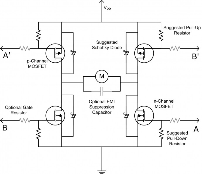
Working principle: Arduino gives a pwm signal that is two times more frequent than the desired, because the same pwm will control both half cycles of AC signal. The CD4013 inverts the output with each rising edge (that's why duty ratio is limited up to %99.6 but not %100). The 74HCT08 is just an "and" gate and it forces the output to turn off when there is no input from Arduino, that allows me to control the duty ratio. pin10 and !pin10 are the outputs of the and gates and they are applied to MOSFET drivers. Duty cycle of PWM is related to PWM signal frequency, there is a constant V/Hz ratio "220/50 = 4.4" to not overheat or underdrive the fan.
While I was testing the circuit, I used an 220V neon light instead of a fan. I noticed that the light didn't light up, probably MOSFETs wasn't firing. I saw 310V across the capacitor as expected but the load wasn't taking it. One more thing I noticed was that when I plug the Ac input to wall, the Arduino turns on but the OLED screen displayed only a portion of the text and rest of the screen was whitish grunge image. This didn't occur with USB connection. I thought It was because of the unstable voltage at the first instance when I plug in. I didn't care much because the screen was normal when the second page is loaded. The sensors were giving normal measurements and the display was showing that normal AC frequencies were being applied by Arduino.
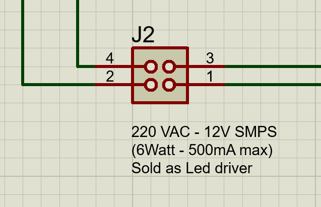
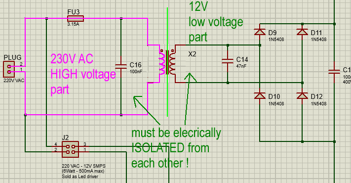
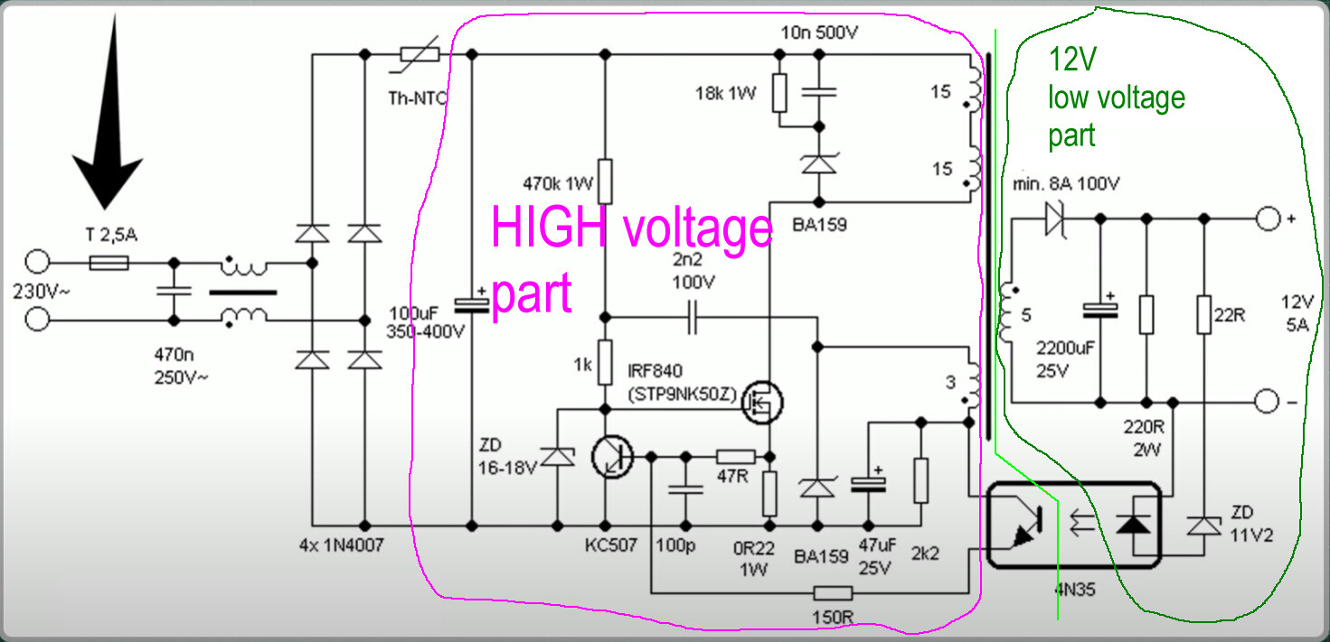
I prepared to take measurements, I plugged in the system this time I saw that power supply LED, Arduino power LED and Sensor LED was blinking. I was surprised, I thought the power supply was corrupted and it was giving positive output then zero output in turns. I plugged out but I couldn't think of what to do so I plugged it back in. The blinking occurred again, I didn't care this time, I just wanted to take measurements from H bridge so I approached the system. When I sat down near it I realized a burning smell, I ran and unplugged the system. I thought the power supply was just dead, it was a cheap low power supply after all (12V 6Watt 0.5amps LED driver).
Btw I was constantly touching the IR2110, CD4013, 74HCT08N and Atmega chip after I plugged out the system. They weren't hot. I didn't touch the voltage regulator during tests but I remember I felt hot air over it, I was even concerned if it was going to affect the temperature sensor, I wasn't more concerned.
I waited the capacitor to discharge then I connected the Arduino with USB, I touched the regulator and it burned my finger. I removed the power supply and tested the Arduino solely, it burned my finger again. I turned my focus onto the power supply, tested the power supply with multimeter and a 12V LED and surprisingly it was working perfectly. I measured the resistance between Arduino VCC and GND pin and it was only 10 ohms, something was basically penetrated by current (if that's the right term) I removed the regulator and this time I saw only 18 ohms. I plugged in the USB cable, as there was no voltage regulator, this time, the ATmega chip was burning. I desoldered everything that's connected to VCC pin but still the resistance between VCC and GND was 18 ohms. The MOSFET drivers (IR2110) are completely fine. I checked the resistance between their output and ground pins, it was large.
On the voltage regulator it says: 4MBD and I don't know what model that is.
My question is: What could possibly cause the Arduino to burn like that? Cheap Arduino clone has a poor regulator that can't keep up with 12V Raw input? The cheap Led driver has voltage spikes at start up and that killed the regulator? The 310 DC Voltage was finding a way to Arduino (this option is unlikely because Arduino performed normal for some time during tests, if 310V were there it would die instantly right, also no led or screen was brighter than it should've been)?