Why is magnetometer stronger on one side than the other?

I recently bought a Pololu L1S3MDL magnetometer. Here is the datasheet:

[https://www.pololu.com/file/0J1089/LIS3MDL.pdf] (https://www.pololu.com/file/0J1089/LIS3MDL.pdf)

I found enough code online to put some code together to get readings. The L1S3MDL library is also from Pololu. Here is the code: (I just edited it to make it easier to read.)

#include <Wire.h>
#include <LIS3MDL.h>

LIS3MDL mag;

const int      relayPin       = 7;           // Define your relay pin here
const int      numReadings    = 100;
float          magXOffset     = 0, magYOffset = 0, magZOffset = 0;

int            led            = 13;

const int      dipSwitchPin   = 8;           // Define your dip switch pin here
const int      nearThreshold  = 300;         //Set close theshold to trigger value// Adjust these values as needed
const int       farThreshold   = 500;        //Set far away threshold to trigger value// Adjust these values as needed

void setup() {
  Serial.begin(9600);
  Wire.begin();

  pinMode(led,OUTPUT);
  digitalWrite(led,LOW);
  
  if (!mag.init()) 
  {
    Serial.println("Failed to detect the LIS3MDL magnetometer.");
    while (1);
  }
  
  mag.enableDefault();

  calibrateMagnetometer();

  pinMode(relayPin, OUTPUT);
  digitalWrite(relayPin, LOW);                    // Ensure relay is off
  pinMode(dipSwitchPin, INPUT);                   // Set dip switch pin as input
}

void calibrateMagnetometer() 
{
  long magXSum = 0, magYSum = 0, magZSum = 0;
  const int calibrationReadings = 1000;
  
  for (int i = 0; i < calibrationReadings; i++) 
  {
    mag.read();
    magXSum += mag.m.x;
    magYSum += mag.m.y;
    magZSum += mag.m.z;
    delay(10); // Small delay between readings
  }
  
  magXOffset = magXSum / calibrationReadings;
  magYOffset = magYSum / calibrationReadings;
  magZOffset = magZSum / calibrationReadings;
}

void loop() 
{
  long magXSum = 0, magYSum = 0, magZSum = 0;

  for (int i = 0; i < numReadings; i++) 
  {
    mag.read();
    magXSum += (mag.m.x - magXOffset);
    magYSum += (mag.m.y - magYOffset);
    magZSum += (mag.m.z - magZOffset);
    delay(10);                               // Small delay between readings
  }
  
  float avgMagX = magXSum / numReadings;
  float avgMagY = magYSum / numReadings;
  float avgMagZ = magZSum / numReadings;
  float avgMagnitude = sqrt(sq(avgMagX) + sq(avgMagY) + sq(avgMagZ));
  
  int dipSwitchState = digitalRead(dipSwitchPin);
  float threshold = (dipSwitchState == HIGH) ? nearThreshold : farThreshold; 
  
  if (avgMagnitude > threshold) 
  {
    digitalWrite(relayPin, HIGH);            // Trigger the relay
    digitalWrite(led,HIGH);                  //Trigger on board LED
  } 
  else 
  {
    digitalWrite(relayPin, LOW);             // Turn off the relay
    digitalWrite(led, LOW);                  //Turn off on board LED
  }


  Serial.println(avgMagnitude);
  delay(500);                                // Wait 1/2 second before repeating
}


I have not yet incorporated the dipswitch into the circuit. Here is a pic of the circuit:

5 volts from arduino to VIN. GND to GND. SCA and SCL to A4 and A5.

My ultimate goal is to trigger a relay when a certain threshold value is reached. Ultimately the threshold will be determined with a dipswitch to use a near or far value of magnitude. This will be used to detect a car, then the relay will be triggered to do something else.

In the setup I have a calibrate function that seems to work. Basically when I place the magnetometer anywhere and reset the arduino it WILL calibrate to the new location and show average magnitudes below 100. Usually below 60. I am good with that.

Here is my question...Why when I calibrate it to an area and move it toward my pickup, the magnitude values climb slowly if I keep the magnetometer pointed in the same direction as when I calibrated it, but when I rotate it 180° and approach my pickup it climbs very rapidly from a further distance away? If I keep the magnetometer aligned in the same direction as calibration when I approach the vehicle, it might hit 1,000 or 1,500 average magnitude within a few (3-5) feet. (1-1.5 meters). But if I rotate the magnetometer 180° after calibration, the magnitude will climb over 3,000 at 10-15 feet (3-5ish meters) away and over 6,000 at 2-3 feet away from the pickup.

Edited again for further clarification: I want to lay this parallel with my driveway and then calibrate it in the parallel position, at which point I will leave it there. But it seems as if the sensitive side will be on the yard side of the magnetometer, not the driveway side. I need the driveway side to be the sensitive side. I know it seems as if I could just turn it 180° and recalibrate it, but refer back up to the paragraph above.

Could it possibly be caused by calibrating it to close to the pickup so the pickup is calibrated into one side of the magnetometer? Do I need to move the pickup way far away for initial calibration? Now that I think about it...that's possible.

Any thoughts? I am trying to understand this. Thank you.

Magnetometers need to be carefully calibrated to be useful, and the method you chose is not correct. This excellent tutorial goes over all the details.

A fully worked example can be found here, for a particularly difficult case.

1 Like

I have read through those multiple times while researching this project I am working on. There is WAY MORE info there than a newby can absorb! But this newby is trying.

I have also read through other posts on this forum and the Pololu forum that you and others have posted about different magnetometers. In fact I looked at many different magnetometer models. If I remember right, I read somewhere you recommended this one and it seemed to have plenty of documentation. That is why I chose it. But it does not seem to have as much forum presence as some other models.

I did try the Calibrate program in the balboa_mag.zip file that you made. Please correct me if I am wrong. It seems to indicate direction/rotation change more than changes in magnetic field. If my understanding is correct (and that is why I am asking, because I am not sure and trying to learn), detecting change in rotation is based off of where the magnetometer position is in relation to the earth's magnetic field. But that seems to be more for using it as a compass, not a magnetic field indicator.

I am unsure how to use the values from the calibrate program to indicate whether or not a vehicle is nearby. The serial prints seemed to indicate more change from turning the LIS3MDL, not how close it was to a large metal object. There was some variance in the readings when approaching vehicles, but not much at all verses rotating it as I was walking around with it. Can I use the library and change the sensitivity?

And lastly, if using it as a magnetic field indicator, does it NEED to be calibrated like a compass? I only ask not to argue, but to understand. In my possible ignorance, I was thinking that it just would need a calibration to it's surroundings where it will be used. I reasoned this based off of two ideas. #1-It is not being built to indicate direction. Once it is laid at its permanent location it is staying there, not moving. And #2-If it is placed near buried electric lines, or metal fence, etc...it would already be "zeroed" to that area and recognize when something new and metal comes near it.

What changes? In the absence of iron, electric currents or magnetized objects, the Earth's magnetic field is a constant over a given region.

If you are trying to detect cars, then the iron in them distorts the Earth's field by changing its direction in a difficult-to-predict fashion. About all you can do is detect changes in all three axes.

It is not very clear what you want to do, and if you could take a few moments to better describe the project, that might help.

Hi, @scottcalv

A car not a magnet, so will not supply its own field sufficiently to give you appreciable changes in value of the mag field.
Most front and rear end parts these days are plastic as well.

Your magnetometer when sitting with no magnets around it, will sense the weak earth's field.
A lump of metal, like a car will distort the field the sensor is measuring, however that change may not be enough to be reliably detected and consistently.

That is why at traffic lights there are large coils under the road to detect a vehicle.

If I was you I would be getting your project out into the garage.
Experiment to see how much change you get when you position the sensor where you want it to be and approach with a vehicle.

Tom.... :smiley: :+1: :coffee: :australia:

1 Like

The major changes in readings I see in the serial monitor are more related to turning/spinning/rotating the magnetometer. The changes I see in the serial monitor are very minor when a heavy metal object is nearby.

That was why I was averaging those 3 axes and using that average to set a threshold to trigger. If any one axis changed, it would change the average.

It is not very clear what you want to do, and if you could take a few moments to better describe the project, that might help.

There are commercial units for this application. I just want to build one (to learn more about programming and electronics, PLUS it's fun) instead of buy one. It will be hardwired to my gate opener. The sensor and arduino will be buried in an irrigation box beside the driveway in a sealed plastic container and hardwired to the gate operator. Thus the reason for wanting to calibrate the unit in place where it will be used.

The hardwiring will have 4 wires. The gate opener has a 500 mA terminal to pull 12 volt + and - power from. The two power wires are one positive DC voltage (12 volts) from the operator to the arduino and one negative DC from the operator to the arduino. The other 2 wires are wired to an approximate 6 volt supply from the operator exit terminals to a relay controlled by the arduino and back to the operator. The relay will also be in the sealed box. When the relay is closed, it will connect the two terminals on the control board, triggering an exit. Just like a push button. My plan is to control the relay on/off action with readings from the magnetometer as a vehicle approaches the magnetometer. When a threshold is met, trigger the relay. It only needs a split second of connecting the wires (via relay, or possibly a transistor) to trigger the exit command on the gate operator control board. This gate opener is a global company who is well known in the States. This is a very quality company. I am pretty familiar with how it works. If you have questions please ask. I can talk gate openers all day!

My "car" is a one ton pickup. There is plenty of iron in it. But I was hoping that much mass would deflect the earth's field enough to be detected. And it IS detected, but detection comes with problems. Problem #1 is I do not get consistent readings when pulling the pickup up to all 4 different sides of the magnetometer. But there is not a consistent more sensitive side. I have proven this with other metal objects and magnets as well. Problem #2 is sometimes the average magnitude actually drops when the vehicle is pulled near it. Once again with no rhyme or reason. If it drops, it will never hit the threshold to trigger the relay.

I am very familiar with inductance loops. I build and install gates and gate automation for a living. Sometimes a customer (me in this case) has a gravel driveway. On occasion, even after laying the inductance loop in conduit, gravel can get crushed through it and short the loop. I know from experience. Especially with large pickups and big trucks driving over it. Plus I do not want to trench up my drive to install the loop.

Believe me I have. That is how I know what the numbers are doing.

I will take more suggestions, but in the meantime I am going to play with the axis values some more. I am also going to get a longer USB cable so I can calibrate it further away from my computer. Maybe the laptop is throwing it off some. I am using the laptop to take it outside and drive beside it and read the serial monitor. Does anyone suspect the laptop is messing with my readings? My USB cable is only about 20" long or so.

Thanks.

Why do you need to approach from 4 different sides?
Can you please tell us the scope of your project?

Tom... :grinning: :+1: :coffee: :australia:

No surprise there. The distortions in the Earth's field caused by a large irregular iron object are very complex.

I've done a gate opener using a magnetometer, and it worked well, The approach that worked best was to measure the squared distance from the "current point in 3D magnetometer space" to the "average point", average determined over a long period of time using an exponential filter.

When that squared distance exceeds a particular empirically determined value for more than say 2 or 3 consecutive samples, a vehicle is detected. It never missed a passing vehicle, but the magnetometer had to be within a couple of meters of it.

The basic idea is in outline very simple:

float dist_squared = (magx - magx_avg)*(magx - magx_avg) + (magy - magy_avg)*(magy - magy_avg) + (magz - magz_avg)*(magz - magz_avg);
if (dist_squared > threshold) sound_alarm();
2 Likes

you might find a single axis magnetometer like ALT021-10E
easier to deal with

In an actual working environment I do not need to approach it from four sides. Only one side. I was experimenting to see if one side delivered more consistent reliable results than another side. When I changed the code, I did the same kind of tests so I was comparing apples to apples.

As far as the scope of the project, feel free to ask questions but I thought I explained it pretty well in post #6 above. Maybe I did not explain as well as I thought I did.

Ok good. Maybe I am not doing anything inherently wrong. From all of your posts I have read through different forums, your observations are definitely based on real world experience.

I was thinking of something similar, but was not sure how to implement it. I will try this addition to the code later when I can.

There is one commercial unit in particular that is extremely sensitive. It can detect cars from up to 15 or 20 feet away. It can even detect if you are walking near by with a shovel in your hand. I am pretty certain it has a magnetometer in it, though the electronics are sealed in epoxy so I do not know for sure. Two meters distance will be acceptable in my project though.

I will check that one out as part of my learning experience. Do you have experience with this one? Is there a particular supplier that is better than another? I might have seen that one at NVE, but I do not remember. NVE had one I was considering as well.

Edited--The one I was looking at from NVE is ALT521-10E-EVB01: Ultrasensitive Two-Axis Rotational Sensor Breakout Board. It was recommended by NVE for my specific project. I did not buy it yet because I already had the LIS3MDL on the way. But I have been considering it...

Have all your test been performed with the module plugged into a solderless breadboard?

Yes all tests have been performed with the exact same setup you see in the picture in the first post. Nothing on that board has moved from its position that is in the picture. When performing the actual tests I do have to put that breadboard on my laptop to be able to walk around with everything and watch the results on the serial monitor. But I am careful to locate the breadboard on the same corner of the laptop every time. There's no doubt in my mind that where I set it on the laptop will skew the results. Even if it's just a fraction of an inch difference I'm sure it will give a different result every time. But it's the best I have to work with.

I am currently working on new math by squaring the results. Initial tabletop tests look promising. I have not had a chance to get it outside and get it in the real world yet. But so far when I bring things like the computer mouse or my cell phone or a bundle of wires and other odds and ends near and further away from it I'm getting some results that I actually like seeing. When I square the magnitudes it gets the printable numbers up in a range to where I can actually possibly set a threshold to trigger the relay.

What I need is to come up with a value after the calibration. A calibrationValue perhaps. And then my threshold to trigger the relay can be calibrationValue plus a constant number or times a constant number. Whichever way it works best.

The reason I say I need a calibration value is because wherever I calibrate it whether it is on the kitchen table or out by the driveway or in the garage etc it starts out counting at a different magnitude. Without taking a laptop out to where I install it I won't know the magnitude to set the thresholds. So if I can lock that calibration into a value I can use that value in the program to set the threshold.

Does that make sense?

My "3D distance squared" approach does not require magnetometer calibration, as only differences are measured. Setting the threshold for vehicle detection is done by experiment, with the sensor mounted where it will be used.

If it will be outdoors, get rid of the breadboard, as a weatherproof enclosure is required.

i got a ALT021-10E-EVB02 TMR magnetometer evaluation board from nve
it can detect a moving magnet at distances approaching 600mm easily, it has a simple ratiometric analog output, dead simple to use and quite sensitive. never tried sensing a car with it , but its worth a try , it will definitely sense arrival and departure of a magnetic field, steady state, i'm not 100% sure unless its fairly close to the car maybe 100mm or so

I'm sure it will, so why is a surprise that you get different results when you rotate it 180 degrees. Plus the breadboard itself is full of metal strips.

It's not a surprise anymore really. It was at first. Because I was not rotating the module ON the laptop. I was rotating my body while holding the laptop. I was expecting to have a similar reading in a similar point in space. But I am learning that the earth's magnetic field is NOT stable anywhere. And the magnetometer is very sensitive to any amount of tilt or rotation. VERY sensitive. It is a learning experience.

This I did not consider at all. I am going to be busy this week but I will work on getting the circuit built and a plastic container made up to hold it. That will certainly help. Although I like being able to watch the numbers on the serial monitor while I am using it. In this case I may not be able to have my cake and eat it to. But that is ok.

I can program it, implement it, observe it, and change the parameters as needed until it is working like I want it. Last night I put an led on the relay circuit to make it light up when I drove my wife's little car past it. There is not much ferrous metal in it at all. Lots of plastic, fiberglass, and aluminum. One time I achieved a distance of about 6 -7'. This is promising.

More table top tests reveal that I probably need to clean my code up and get the delays() out of there. I think they are causing me problems with triggering the relay circuit. So I will get my delays switched over to millis timers. The delays might not need to be in the code at all. I just read on the internet that if you don't use a small delay between readings then the magnetometer chip can get overwhelmed while trying to read so quickly. This could lead to skewed results. Are there any thoughts on that?

It is remarkably stable. People have navigated using it for thousands of years.

Over decades, the locations of the poles do wander by a fraction of a degree, and for reasons no one understands, every few hundred thousand years it actually reverses! Then everyone has to recalibrate their compasses.

True enough! Maybe the problem is my programming is not stable anywhere! HA. I am getting it down though.

I have replaced all delays with millis timing. I DEFINITELY notice a HUGE difference in my relay circuit. Now my relay is not missing a beat AND the average magnitudes seem to have smoothed out a little in the serial monitor.

Next up is getting it off of the breadboard. Maybe those metal strips mentioned earlier are causing some erratic averages. I want the average magnitudes smoothed out because they jump from around 20 up to 60-70. When they jump up high, it causes the relay to trigger. If I increase the trigger threshold, it loses some sensitivity in the form of distance to the magnetometer. I have to be closer to trigger it. If I increase (using math cubed or doubled, etc...) the detectable value, thus being able to increase the threshold further away from the peak averages, then the detectable numbers OVF or overflow.

So next up, removing the solderless breadboard. If that does not help it get better I will post my newest code and ask for a little more help here on the forum. But either way, good or bad, I will update.

Ok I am back to working on this project. I do not have it running properly yet. Here is the latest code I am working with:

//-----C A R  D E T E C T O R-------for automatic gate-------------------
//FEB 15, 2025

//Detect presence of vehicle by sensing change in earth's magnetic field
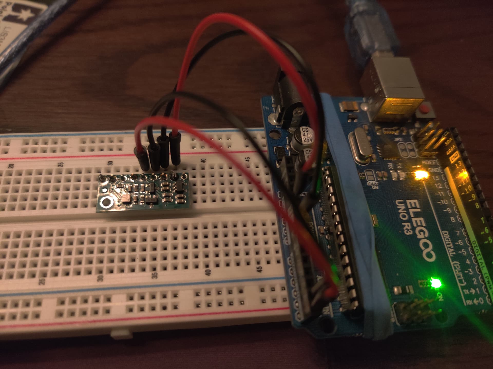
/*Hardware
     --Arudino Nano
     --LIS3MDL board from Pololu
     --SPDT relay with diode
*/

/*------NOTES----------------------------------------------------------
     FEB 16, 2025                  Added buzzer for audible testing.
*/

//-----INCLUDE LIBRARIES---------------------------------------------------
#include <Wire.h>
#include <LIS3MDL.h>

LIS3MDL mag;                       //Make object to communicate with LIS3MDL library

//-----Standard Variables---------------------------------------------------
const int relayPin = 7;           //Define relay pin
int led = 13;                     //Define pin 13 to turn off onboard LED
                                  //MIGHT consider using 13 as relay pin
const int buzzer = 3;             //Buzzer used for prototyping/testing only. Comment out for final project
int sound = 900;                 //Set buzzer frequency. 4000 is easy to hear.
int buzzTime = 350;               //Set buzz time

bool relayTriggered = false;      //Keep up with relay state. Relay on or off.

//-----Magnetometer Measuring Items-----------------------------------------
const int numReadings = 150;      //Get a number of readings to average together
float magXOffset = 0.0;           //Get offsets to calibrate magnetometer
float magYOffset = 0.0;
float magZOffset = 0.0;

long magXSum = 0, magYSum = 0, magZSum = 0;       //Get axis info
float avgMagX;                                    //Average X, Y, and Z axes
float avgMagY;
float avgMagZ;

int readingsCount = 0;                            // Counter for the number of readings to average

//-----Math Formulas---Formulated in loop-------------------------------------
float avgMagnitude;                               //Average X, Y, and Z into one average value
float comparativeValue;                           //Value to comapre to threshold
float threshold;                                  //Trigger relay if far away from magnetometer
float calibratedAvgValue;                         //Determined in calibrateMagnetometer() and used to determine trigger thresholds

//-----Timing-------------------------------------------------------------------
const int printDelay = 200;                       //Delay between serial prints
const int readingInterval = 1;                    //Interval between readings
unsigned long previousReadingMillis = 0;          //Store the last time a reading was taken. For Reading mag
unsigned long relayTimer = 0;                     //Relay trigger timing
const int relayDelay = 2000;                      //Amount of time relay is on in milliseconds
unsigned long previousResetMillis = 0;            //Store last time magnitude reset happened
const int resetDelay = 2000;                      //Reset avgMagnitudes every 1 seconds

//-----Low-pass filter variables--------------------------------------------------
//Smooth out readings by eliminating highest mag and lowest mag reading
float filteredX = 0.0;
float filteredY = 0.0;
float filteredZ = 0.0;
float cutoff = 0.1;                              /* Cutoff frequency (how aggressive the filter is). 
                                                  Smaller number = more aggresive but more lag*/

//-----E N D  O F  V A R I A B L E S----------------------------------------------

void setup() {
  Serial.begin(9600);                             //Start Serial monitor
  Wire.begin();                                   //Initiate I2C comms

  pinMode(led, OUTPUT);                           //Turn off on board pin 13 LED. MIGHT use
  digitalWrite(led, LOW);                         //for relay so LED lights when relay is triggered

  pinMode(buzzer, OUTPUT);                        //Set up buzzer. Comment out for final project


  if (!mag.init()) {                              //Tell me if program can't find magnetometer
    Serial.println("Failed to detect the LIS3MDL magnetometer.");
    while (1)
      ;
  }

  mag.enableDefault();                            //Default library values

  calibrateMagnetometer();

  pinMode(relayPin, OUTPUT);
  digitalWrite(relayPin, LOW);
}

void calibrateMagnetometer() {
  long magXSum = 0, magYSum = 0, magZSum = 0;
  const int calibrationReadings = 500;
  for (int i = 0; i < calibrationReadings; i++) {
    mag.read();
    magXSum += mag.m.x;
    magYSum += mag.m.y;
    magZSum += mag.m.z;
    delay(2);
  }

  magXOffset = magXSum / calibrationReadings;
  magYOffset = magYSum / calibrationReadings;
  magZOffset = magZSum / calibrationReadings;

  calibratedAvgValue = sqrt(magXOffset * magXOffset + magYOffset * magYOffset + magZOffset * magZOffset);
}

//-----E N D  O F  S E T U P------------------------------------------------------

void loop() {
  unsigned long currentReadingMillis = millis();                 //Start timer to collect readings

  if (currentReadingMillis - previousReadingMillis >= readingInterval) {
    previousReadingMillis = currentReadingMillis;

    mag.read();
    // Apply low-pass filter
    filteredX = filteredX + cutoff * (mag.m.x - filteredX);
    filteredY = filteredY + cutoff * (mag.m.y - filteredY);
    filteredZ = filteredZ + cutoff * (mag.m.z - filteredZ);

    // Calculate magnitude of filtered values

    magXSum += (filteredX - magXOffset);                         // Add the filtered values to the sums for averaging later
    magYSum += (filteredY - magYOffset);
    magZSum += (filteredZ - magZOffset);

    readingsCount++;                                             //increment reading count
  }

  if (readingsCount >= numReadings) {                            //When numReadings had been reached...
    avgMagX = magXSum / numReadings;
    avgMagY = magYSum / numReadings;
    avgMagZ = magZSum / numReadings;

    avgMagnitude = sqrt(sq(avgMagX) + sq(avgMagY) + sq(avgMagZ)); //Get avgMagnitude

    comparativeValue = sq(avgMagnitude)*4;                        //Compare to threshold

    magXSum = 0;                                                  // Reset sums after averaging
    magYSum = 0;
    magZSum = 0;
    readingsCount = 0;                                            // Reset readings counter

    threshold = calibratedAvgValue*30;
  }

  //-----RELAY TRIGGER CONTROL---------------------------------------------

  if (comparativeValue > threshold && !relayTriggered) {

    //digitalWrite(relayPin, HIGH);
    digitalWrite(led, HIGH);
    tone (buzzer, sound, buzzTime);
    relayTriggered = true;
    relayTimer = millis();
    avgMagnitude = 0;
  }

  if (relayTriggered) {
    unsigned long currentRelayMillis = millis();
    if (currentRelayMillis - relayTimer >= relayDelay) {
      //digitalWrite(relayPin, LOW);
      digitalWrite(led, LOW);
      noTone(buzzer);
      relayTriggered = false;
    }
  }

  if (avgMagnitude < threshold && !relayTriggered) {
    //digitalWrite(relayPin, LOW);
    digitalWrite(led, LOW);
  }

  //-----RESET MAGNITUDES TO PREVENT CREEPING UP OVER TIME---------------------------
  if (!relayTriggered) {
    unsigned long currentResetMillis = millis();
    if (currentResetMillis - previousResetMillis >= resetDelay) {
      previousResetMillis = currentResetMillis;
      avgMagnitude = 0;
    }
  }

  //-----DO SERIAL PRINTS-----COMMENT OUT FOR FINAL UPLOADED CODE-------------------
  unsigned long checkPrintTime = millis();
  static unsigned long oldPrintTime;
  if (checkPrintTime - oldPrintTime >= printDelay) {
    oldPrintTime = checkPrintTime;
    Serial.print("calibratedAvgValue=  ");
    Serial.print(calibratedAvgValue);
    //Serial.print("  nearThresh= ");
    //Serial.print(nearThreshold);
    Serial.print("  Thresh=  ");
    Serial.print(threshold);
    Serial.print("  AvgMag= ");
    Serial.print(avgMagnitude);
   // Serial.print("  AvgOfAvgs= ");
   // Serial.print(avgOfAverages);
    Serial.print("  ComparativeValue= ");
    Serial.println(comparativeValue);
  }
}

And here is a screenshot of a few serial printouts:

calibratedAvgValue=  3348.01  Thresh=  100440.28  AvgMag= 83.48  ComparativeValue= 27876.00
calibratedAvgValue=  3348.01  Thresh=  100440.28  AvgMag= 111.40  ComparativeValue= 49640.00
calibratedAvgValue=  3348.01  Thresh=  100440.28  AvgMag= 111.45  ComparativeValue= 49688.00
calibratedAvgValue=  3348.01  Thresh=  100440.28  AvgMag= 85.09  ComparativeValue= 28964.00
calibratedAvgValue=  3348.01  Thresh=  100440.28  AvgMag= 116.20  ComparativeValue= 54008.00
calibratedAvgValue=  3348.01  Thresh=  100440.28  AvgMag= 125.64  ComparativeValue= 63140.00
calibratedAvgValue=  3348.01  Thresh=  100440.28  AvgMag= 92.36  ComparativeValue= 34124.00
calibratedAvgValue=  3348.01  Thresh=  100440.28  AvgMag= 93.55  ComparativeValue= 35008.00
calibratedAvgValue=  3348.01  Thresh=  100440.28  AvgMag= 95.26  ComparativeValue= 36296.00
calibratedAvgValue=  3348.01  Thresh=  100440.28  AvgMag= 133.93  ComparativeValue= 71748.01
calibratedAvgValue=  3348.01  Thresh=  100440.28  AvgMag= 122.40  ComparativeValue= 59928.00
calibratedAvgValue=  3348.01  Thresh=  100440.28  AvgMag= 107.50  ComparativeValue= 46224.00
calibratedAvgValue=  3348.01  Thresh=  100440.28  AvgMag= 124.92  ComparativeValue= 62424.00
calibratedAvgValue=  3348.01  Thresh=  100440.28  AvgMag= 114.17  ComparativeValue= 52136.00
calibratedAvgValue=  3348.01  Thresh=  100440.28  AvgMag= 0.00  ComparativeValue= 33876.00
calibratedAvgValue=  3348.01  Thresh=  100440.28  AvgMag= 130.28  ComparativeValue= 67892.01
calibratedAvgValue=  3348.01  Thresh=  100440.28  AvgMag= 120.77  ComparativeValue= 58340.00

And here is some of my reasoning behind the coding you see:

#1- I am calibrating in the setup because I have determined that different locations will have different values. I have used the serial monitor and restarted the arduino all over my place. The different calibratedAvgValue has ranged from around 3000 up to 8000. So instead of just having an arbitrary threshold value, I want it calibrated to the exact location that it will be used in. This idea seems to work during testing.

#2- I am using the higher comparativeValue because it seems to be easier to fine tune the threshold using larger numbers.

#3- And speaking of threshold this is the battle and has been the battle...I am resetting the avgMagnitude every couple of seconds to zero BECAUSE the readings creep higher over time, causing false alarms. It might run 2 minutes without a false alarm. Or it might run 2 hours without a false alarm. But it WILL eventually have a false alarm. Resetting to zero does seem to help but is not failproof.

In the screenshot of the serial monitor, you can see readings all over the map. The avgMagnitude 0.00 is probably due to resetting it every two seconds. I could not catch it in time BUT twice in about a minute the comparativeValue HAD to have creeped over the threshold value because I heard the beeps while I was doing something else. (That is why I put the buzzer on it. So I can do other tasks and not have to monitor the monitor or LED.) That means it got over 100,440.28 with no change in the environment around it.

Is this normal?? Am I expecting to much precision and should I just set my threshold higher and live with it? Or is the L1S3MDL unstable? Or am I just absolutely horribly doing something wrong? It seems like no matter where I set the threshold value (within reason, obviously I cannot max it out or it won't work at all), at some point it is going to trigger itself without an environmental input. There has to be some unseen environmental input.

I want it to be as sensitive as possible so I can detect as far as possible, but without the false alarms. Is the code ok and I just need to increase the threshold until I quit getting false alarms? I am good with that. I just want to make sure I am not barking up the wrong tree here.

I have tried with the USB hooked to the computer and also with a battery pack out in the yard away from any influence. I get the same results every time. False alarms.

Any thoughts?

Thanks

Here is another shot of the serial monitor:

calibratedAvgValue=  5710.18  Thresh=  216986.96  AvgMag= 115.71  ComparativeValue= 53552.00
calibratedAvgValue=  5710.18  Thresh=  216986.96  AvgMag= 121.70  ComparativeValue= 59240.00
calibratedAvgValue=  5710.18  Thresh=  216986.96  AvgMag= 121.99  ComparativeValue= 59524.00
calibratedAvgValue=  5710.18  Thresh=  216986.96  AvgMag= 159.79  ComparativeValue= 102132.00
calibratedAvgValue=  5710.18  Thresh=  216986.96  AvgMag= 134.32  ComparativeValue= 72168.00
calibratedAvgValue=  5710.18  Thresh=  216986.96  AvgMag= 126.38  ComparativeValue= 63892.00
calibratedAvgValue=  5710.18  Thresh=  216986.96  AvgMag= 120.64  ComparativeValue= 58220.00
calibratedAvgValue=  5710.18  Thresh=  216986.96  AvgMag= 113.56  ComparativeValue= 51588.00
calibratedAvgValue=  5710.18  Thresh=  216986.96  AvgMag= 113.69  ComparativeValue= 51704.00
calibratedAvgValue=  5710.18  Thresh=  216986.96  AvgMag= 105.76  ComparativeValue= 44744.00
calibratedAvgValue=  5710.18  Thresh=  216986.96  AvgMag= 99.53  ComparativeValue= 39628.00
calibratedAvgValue=  5710.18  Thresh=  216986.96  AvgMag= 99.22  ComparativeValue= 39380.00
calibratedAvgValue=  5710.18  Thresh=  216986.96  AvgMag= 90.28  ComparativeValue= 32600.00
calibratedAvgValue=  5710.18  Thresh=  216986.96  AvgMag= 117.96  ComparativeValue= 55656.00
calibratedAvgValue=  5710.18  Thresh=  216986.96  AvgMag= 114.18  ComparativeValue= 52148.00
calibratedAvgValue=  5710.18  Thresh=  216986.96  AvgMag= 81.37  ComparativeValue= 26484.00

You can see swings from 26,484 to over 102,000. The avgMagnitudes in those two cases are 81.37 and159.79. There were no environmental inputs. It is just setting on a tabletop doing its thing.

So are these types of swings normal when there are no magnetic objects or large metal masses around? That is really the question. Or is there an issue with my magnetometer or coding?

EDITED--I had some comparative values jump up over 200,000 about 30 minutes after posting this. I did not catch the avgMagnitudes, but I am sure they jumped up as well. That is why the compValue went up. There were no changes in the environment.

So are these types of swings normal when there are no magnetic objects or large metal masses around? That is really the question. Or is there an issue with my magnetometer or coding?