I2C Device found at address: 0x7F why 0x7f>>>>> plz help
Please don't hijack forum topics @xcode000. I have split your post out to its own topic.
Hijacking is against the Arduino forum rules. The reason is that it may sidetrack the discussion, even preventing the creator of the topic from getting the assistance they need. It also reduces your own chances of getting assistance.
This is basic forum etiquette, as explained in the "How to get the best out of this forum" guide. It contains a lot of other useful information. Please read it.
Thanks in advance for your cooperation.
Because you have an I2C device attached to SCA/SCL and it has a (configurable) address of 0x7f.
According to the I²C standard (UM10204) there are several addresses are reserved. They are as follows:
0x00: General call address
0x01–0x07: Reserved for future use
0x78–0x7F: Reserved (these are not valid normal addresses)
It happens: Some I2C scanners may report a device at 0x7F, but that’s usually:
A false positive (due to pull-ups or noise)
A misconfiguration or faulty device
To answer your question 0x7F is a reserved address and should not be assigned to I2C peripherals. If you detect activity on 0x7F, it’s worth investigating for hardware errors or bus contention.
Right.
Only addresses are excluded where the address byte is not acknowledged by any slave.
“Why is I2C device found at address 0x7F?
What is your device type?
Supposedly
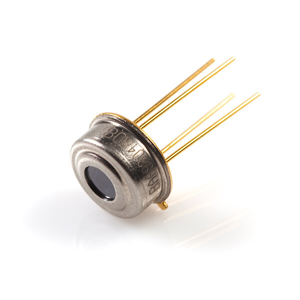
What is the device you have connected? If you're not sure what it is, a picture might help.
Might it be a wrong offset, meaning device 0x00 which is the broadcast address?
mlx90614 with Esp32-S3

I’m using an ESP32-S3 with the MLX90614 infrared temperature sensor but facing continuous communication failure. I’ve tested multiple MLX90614 modules and multiple ESP32-S3 boards. I connected the sensor using I2C with SDA on GPIO 19 and SCL on GPIO 20. Despite trying different GPIO pins and scanning with an I2C scanner, I either get no address or an invalid address like 0x7F, which doesn’t work with any example code. The MLX90614 modules I’m using already have onboard pull-up resistors. I also tried switching between 3.3V and 5V power supplies, but there’s no change in response. The sensor works fine with ESP32-WROOM and Arduino Uno, which rules out faulty sensors. I’ve even tried both Adafruit and SparkFun libraries, but still no success. Now I’m wondering if there’s any I2C level-shifting issue or timing difference with the ESP32-S3 specifically. If anyone has successfully used MLX90614 with ESP32-S3 or has insight into such issues, your help would be appreciated.
I have merged your forum topics due to them having too much overlap on the same subject matter @xcode000.
In the future, please only create one topic for each distinct subject matter and be careful not to cause them to converge into parallel discussions.
The reason is that generating multiple forum topics on the same subject matter can waste the time of the people trying to help. Someone might spend a lot of time investigating and writing a detailed answer on one topic, without knowing that someone else already did the same in the other topic.
Thanks in advance for your cooperation.
I’m using an ESP32-S3 board with the MLX90614 infrared temperature sensor (PCB module version with onboard pull-up resistors). I’ve connected the sensor to GPIO 19 (SDA) and GPIO 20 (SCL). I’ve tried multiple MLX90614 modules and multiple ESP32-S3 boards, but I2C communication doesn’t work at all. The I2C scanner either shows only 0x7F or no address at all.
At which I2C address?
The ESP32-S3 features two I2C controllers that can operate as either masters or slaves. It supports both Standard-mode (100 kHz) and Fast-mode (400 kHz) I2C communication, and can be configured to use 7-bit or 10-bit addressing. The ESP32-S3 also allows for flexible GPIO pin selection for I2C communication through its GPIO matrix.
Key Features:
· Two I2C controllers: Each controller can handle communication as either a master or a slave.
· Flexible GPIO assignment: The I2C pins can be routed to any available GPIO pins using the GPIO matrix, according to the ESP32 forum.
· Standard and Fast modes: Supports both 100 kHz and 400 kHz I2C communication speeds.
· 7-bit and 10-bit addressing: Can communicate with devices using either addressing scheme.
· Master and Slave functionality: Can initiate communication as a master or respond to requests as a slave.
· Pull-up resistors: I2C lines require pull-up resistors, typically between 1k and 10k Ohms, to ensure proper operation. The Espressif documentation recommends choosing a value within 2k to 5k Ohms.
Hardware limitations: The maximum I2C bus speed is also influenced by the pull-up resistor values and wire capacitance.
I am not sure of what you have. please do the following:
1. Annotated Schematic: Post a detailed schematic of your setup exactly as you have it wired, showing all connections, including power, ground, and power supplies.
2. Technical Information Links: For all hardware devices in your circuit, provide links to technical information. Be aware that many items in the Arduino/Pi world may have the same name but function differently. Links to sales pages like Amazon often lack the necessary technical details, so ensure the links you provide contain the correct specifications and data sheets.
3. Be Thorough: It’s your problem, and the more precise and detailed information you provide, the faster we can help you troubleshoot. This saves everyone time and helps us give you the best possible assistance.