Hi so I have a 9V battery on the collector lead and a digital pin controlling the base. Then I was measuring the voltage with my multimeter and saw that the voltage was 4.6 volts. I then put the 5V pin on the base and it was the exact same output. So I'm just wondering why the Transistor is limiting the voltage like this, is the 5v not enough for the base? Or is it doing some sort of voltage divider. Please note I'm not using any resistors on the leads.
Post a schematic of the setup. Hand drawn, photographed and posted is fine. Include all pin labels, part numbers and/or values and power supplies.
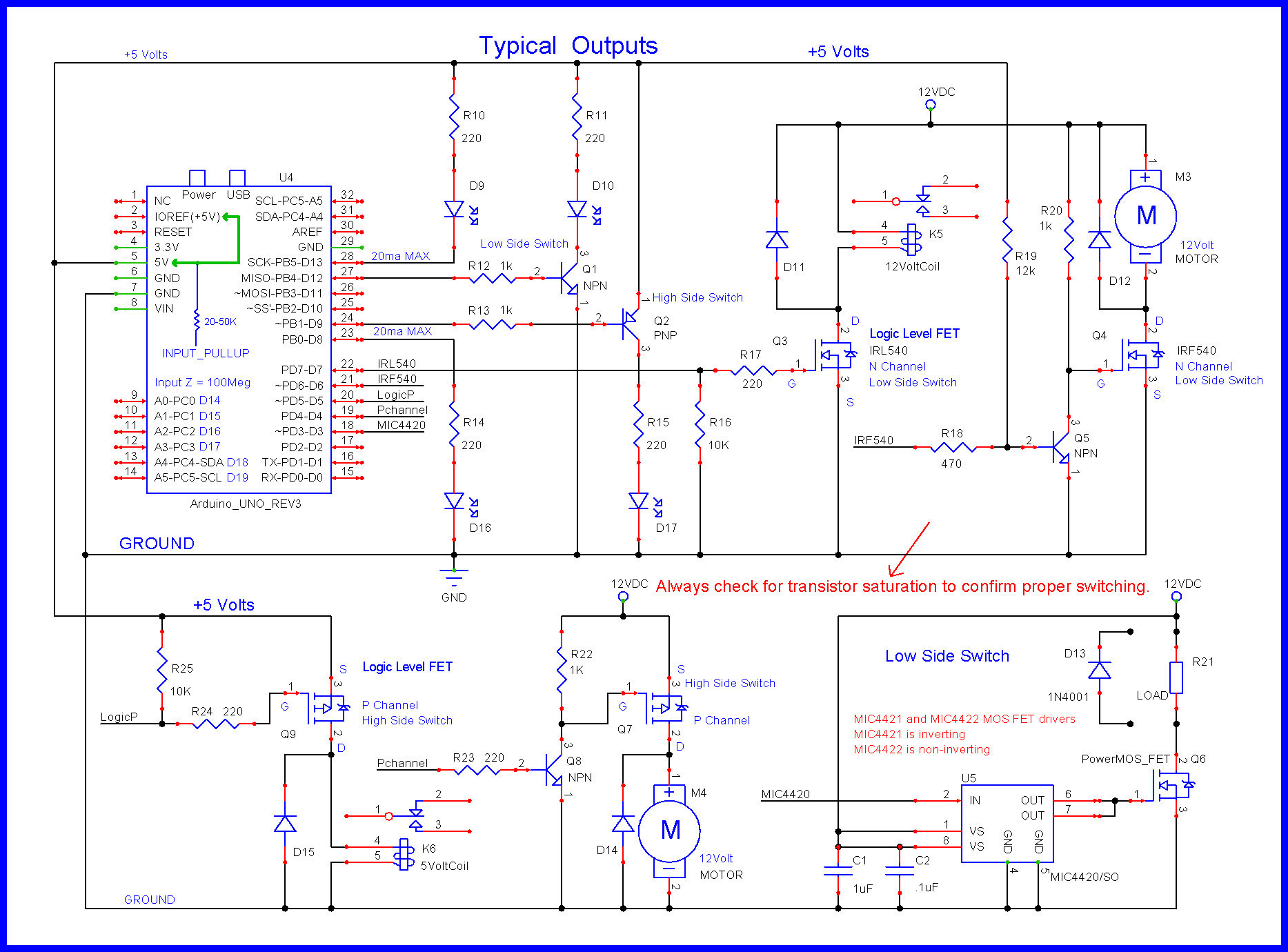
Here are some circuits you can refer to.


"The voltage" where?
From the emmiter to gnd
All it is is a NPN transistor(don’t know which one) with it collector to a 9V battery, base connected to pin A0 and then emitter connected to the multimeter no other components than that
Cause the only PNP I’ve got is in an assortment kit and I was not using this transistor from that

You have wired up an "emitter follower".

The emitter "follows" the base, but as you require about 0.6 V or so between emitter and base to turn the transistor on, then the emitter will follow that much less than the base voltage. That you measure 4.6 V suggests that either you are using an antique germanium transistor, or the base voltage is actually more than 5 V
This circuit is not at all useful for switching things such as LEDs. ![]()
@LarryD, the circuit shown would allow better than 20ma through the emitter-base junction. Seems high.
The gain of the transistor is only 1 (one).
![]()
Yes, this circuit is only for discussion purposes.
Understood. I wanted to note it so OP didn't actually use a 240Ω resistor.
Yes, of course.
However, they could as 20mA base current should not hurt the transistor.
example:
Often I use 20mA base current on a 2N2222 just because I have 1000s of 220Rs laying around.
Actually 240R.
Hi, @8675300
Can you please post a schematic of your project?
Please do not use Fritzy, a hand drawn image will be fine.
Include ALL power supplies, component names and pin labels.
Can you tell us what pert number is printed on the transistor?
Can you please post a picture of your project as it is setup for your test?
Do you have any resistors connected to your transistor?
Thanks.. Tom... ![]()
![]()
![]()
![]()
It is incredibly important to understand the basics of the technology you are experimenting with or bad things will happen: smoke your Arduino or the transistor, both, damage wiring, etc.
A good way is to read, study, and doing problem solutions. Another good way is to run a simulation.

Note that unrestrained, the total current passed is the base current + collector current. The two (2) resistors are in circuit to provide a simple way to add your collector load-resistance and the base current limiting resistance (AVR output current limit is 20mA max.)
Obviously, unless you model battery internal resistance and other limiting electrical properties they will not be taken into account. (Which is why the 9V source is sending 9A through the collector.
$ 1 0.000005 10.634267539816555 43 2 50 5e-11
w 352 256 352 304 1
w 352 224 352 176 1
172 272 176 272 144 0 7 9.025 9.5 0 0 0.5 Collector Voltage
g 352 304 352 320 0 0
t 304 240 352 240 0 1 0.8060084225959697 0.8456493510342122 100 default
w 272 240 304 240 1
r 272 176 352 176 0 1
172 208 240 160 240 0 7 4.42 4.5 0.5 0 0.5 Base Voltage
r 208 240 272 240 0 1
Well I didn’t want to limit the current going through the transistor cause I was trying to have it replace a MOSFET(cause I have a shortage of them right now) but now I see that’s not happening, just gonna order some more now
I was going to suggest that a logic-level MOSFET would be a lot easier to use as a switch.
The scheme presented by LarryD should work perfectly fine. If OP would like to switch a current of more than 1 Amp the mosfet will have the advantage of lower heating.
The OP now has an emitter follower. That is a very useful circuit. But not for switching things...
What I am reading into this, less a schematic, is you have a generic NPN transistor all by itself. May we assume you have common ground? That is the base signal, the 9 volt battery and your meter share a common negative ground? Should that be the case when you measure emitter to ground using your meter the only path to ground for the emitter is through your meter. Should that be true your meter input impedance is the only path to ground from the emitter. Your meter could have for example a 10 Meg Ohm input impedance. Yes, in that case I would expect to see 4.5 volts which is exactly what you see. The 5 volts on the base biases your transistor ON.
Your current will be in nA assuming a 10 Meg Ohm input impedance on your meter, about maybe about 454 nA in a simulation using a common 2N3904 NPN transistor. What were you expecting to see?
Less an actual circuit diagram this is as good as it gets but yes, 4.5 volts sounds about right.
Ron
Ron