Why is Serial Port of ESP32 S2 Mini Board not communicating with MCU after uploading?

1. Being influenced by this thread, I uploaded the following sketch in my ESP32 S2 Mini Board (Fig-1) with a hope that the onboard LED will be blinking at 4-sec interval and the message "Hello" will also appear on the OutputBox of the Serial Monitor 1 (SM1, Fig-2) at the same rate. The LED blinks alright; unfortunately, the message "Hello" does not appear on SM1 (Fig-2).
image
Fig-1:

Sketch:

#define LED 15   //onboard LED

void setup () 
{
  Serial.begin (115200);
  pinMode(LED, OUTPUT);
}

void loop () 
{
  digitalWrite(LED, HIGH);
  delay(2000);
  digitalWrite(LED, LOW);
  delay(2000);
  Serial.println("Hello");
}

2. I started to investiage the case and then changed the Serial.print() command to Serial1.print() command to connect the UART1 Port with GPIO-1/3 (Fig-2) which are (by default) TX0/RX0 lines of UART0. Now, I can exchange message between the MCU and Serial Monitor 2 (SM2, Fig-2) via UART1 (Serial1) and NOT UART0 (Serial).

#define LED 15

void setup ()
{
  Serial1.begin (115200, SERIAL_8N1, 3, 1);  //Bd, Frame, RX1, TX1
  pinMode(LED, OUTPUT);
}

void loop ()
{
  digitalWrite(LED, HIGH);
  delay(2000);
  digitalWrite(LED, LOW);
  delay(2000);
  Serial1.println("Hello");
}

Output on SM2:

23:04:54.214 -> Hello
23:04:58.228 -> Hello
23:05:02.214 -> Hello
23:05:06.204 -> Hello

3. My tentative understandings are:
(1) As conceptually presented in Fig-2, the ESP32 S2 has a built-in USB/TTL converter to demodulate the incoming codes of the sketch, and it is permanently connected with the UART0 Module of the MCU.

(2) There is no TTL/USB converter (marked red-crossed in Fig-2) within the MCU to transfer message/data from MCU to the OutputBox of SM1.
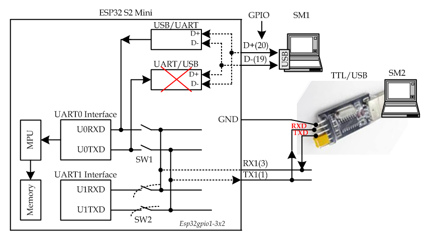

Figure-2:

4. Would be glad to hear from the respected Forum Members.

What are your Tools menu USB settings?

I've already just had a similar experience with a barebones ESP32-C3 Supermini.
Does it work if you drop the attempts to write to Serial ?
Have you tried enabling "USB CDC on Boot" from the tools menu ?
Maybe also try this:
Serial.setTxTimeoutMs(0) ; // Workaround for when USB CDC is unplugged by SuGlider · Pull Request #7583 · espressif/arduino-esp32 · GitHub

This is the settings: (Defaullt settings that auto comes when board is selected.)

I have compiled/uploaded the following sketch with your above code in the setup() function. The LED blinks, but the message (Hello) does not appear on Serial Monitor.

#define LED 15

void setup ()
{
  Serial.begin (115200);//, SERIAL_8N1, 3, 1);
  pinMode(LED, OUTPUT);
  Serial.setTxTimeoutMs(0); //even  Serial.setTxTimeoutMs(1000); does not help
}

void loop ()
{
  digitalWrite(LED, HIGH);
  delay(2000);
  digitalWrite(LED, LOW);
  delay(2000);
  Serial.println("Hello");
}

OK. I've looked more closely. Your case is not exactly the same as mine in that the Serial activity was blocking everything.
I guess you are using the Serial console in the Arduino IDE. You could try changing the baud rate in the console to see if that forces a reset of the device. With native USB, the baud rate should anyway be irrelevant.
Maybe also look here (if you haven't already) Establish Serial Connection with ESP32-S2 - ESP32-S2 - — ESP-IDF Programming Guide latest documentation

there is Serial0 for UART0 if Serial is USB

I have tried Seria0.begin(115200) and Serial0.print("Hello"); the sketch is compoled/uploaded, but the message does not appear on Serial Monitor.

NB: If TTL/USB Converter of Fig-2 of post #1 is not there (my proposition), then there will be no data movement from MCU to SM1 over the UART0 Port!!

In all Arduino Boards and ESP32, the USB Port that is used for sketch uploading is also used for transferring data from MCU to Seral Monitor. The exceptions are:

Digispark ATtiny85 Deve Board (allows only uploading)
image

ESP32 S2 Mini Dev Board (allows only uploading)
image

Finally, the problem is solved having that Serial Port (UART0) of ESP32 S2 communicates in both ways.
IDE 2.2.1 (Apparently, it is IDE 2.2.1 that works and NOT IDE 1.8.19.)

Tools' Menu Settings:
Board selected: ESP32S2 Dev Module
USB CDC On Boot: "Enabled" //Option: Disabled
Port: "COM6"
Upload Mode: "UART0" //option: Internal USB
Sketch is compiled/uploaded

Sketch:

#define LED 15

void setup() {
  Serial.begin(115200);
  pinMode(LED, OUTPUT);
}

void loop() {
  digitalWrite(LED, HIGH);
  delay(1000);
  digitalWrite(LED, LOW);
  delay(1000);
  Serial.println("Hello");
}
Serial Monitor Output along with LED blinking:
11:26:01.625 -> Hello
11:26:03.614 -> Hello
11:26:05.619 -> Hello
11:26:07.631 -> Hello
11:26:09.629 -> Hello

This topic was automatically closed 180 days after the last reply. New replies are no longer allowed.