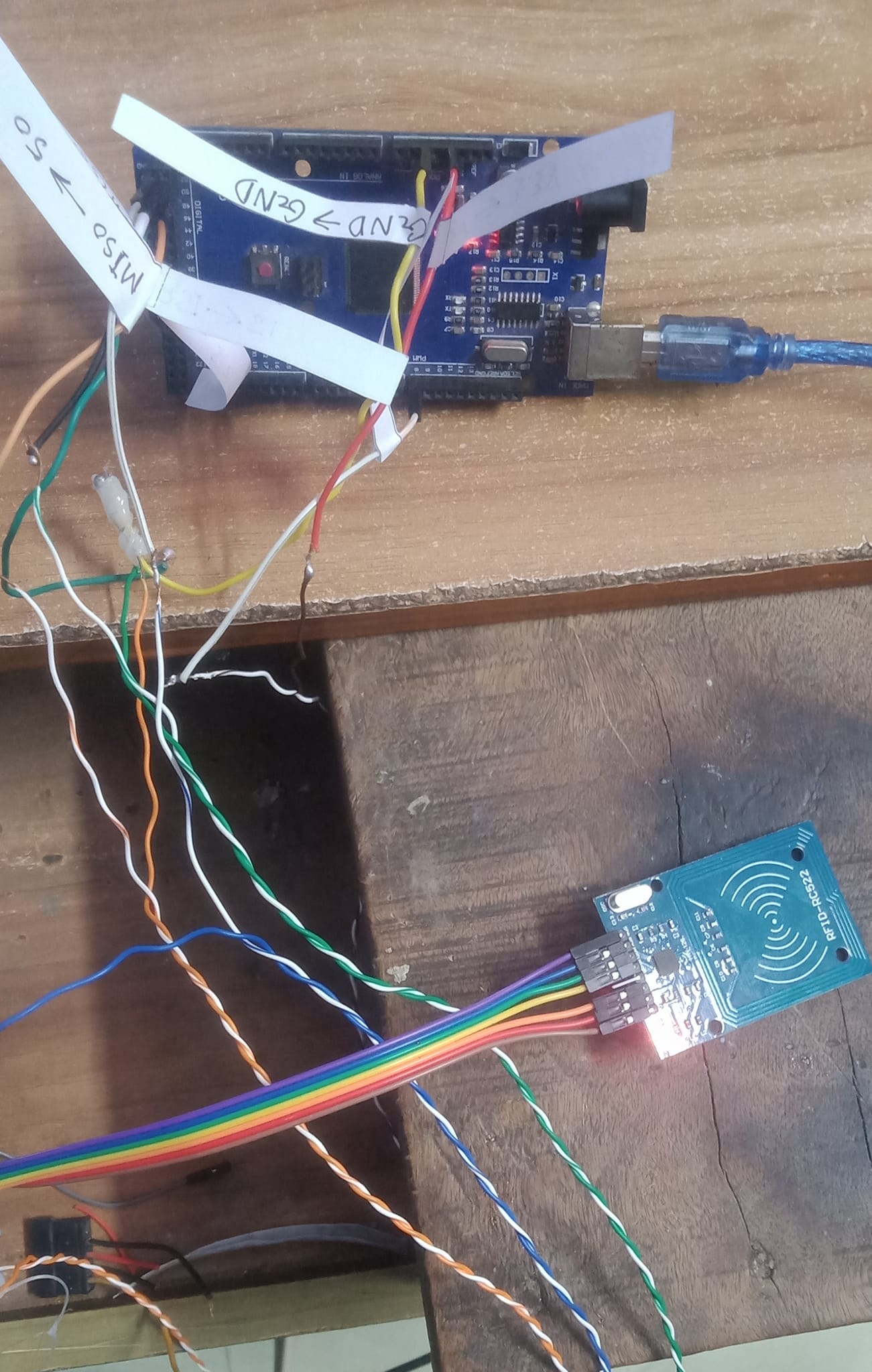
I'm making a project, and in that project there's a part where the RC552 RFID reader will read the RFID tag, and if the tag address is verified, the door will open. I need to place the RC522 about 2 feet besides the Arduino Mega, so I cut the jumper wires and connected CAT6 wire's mini wires, as there is only 1 core wire in them.
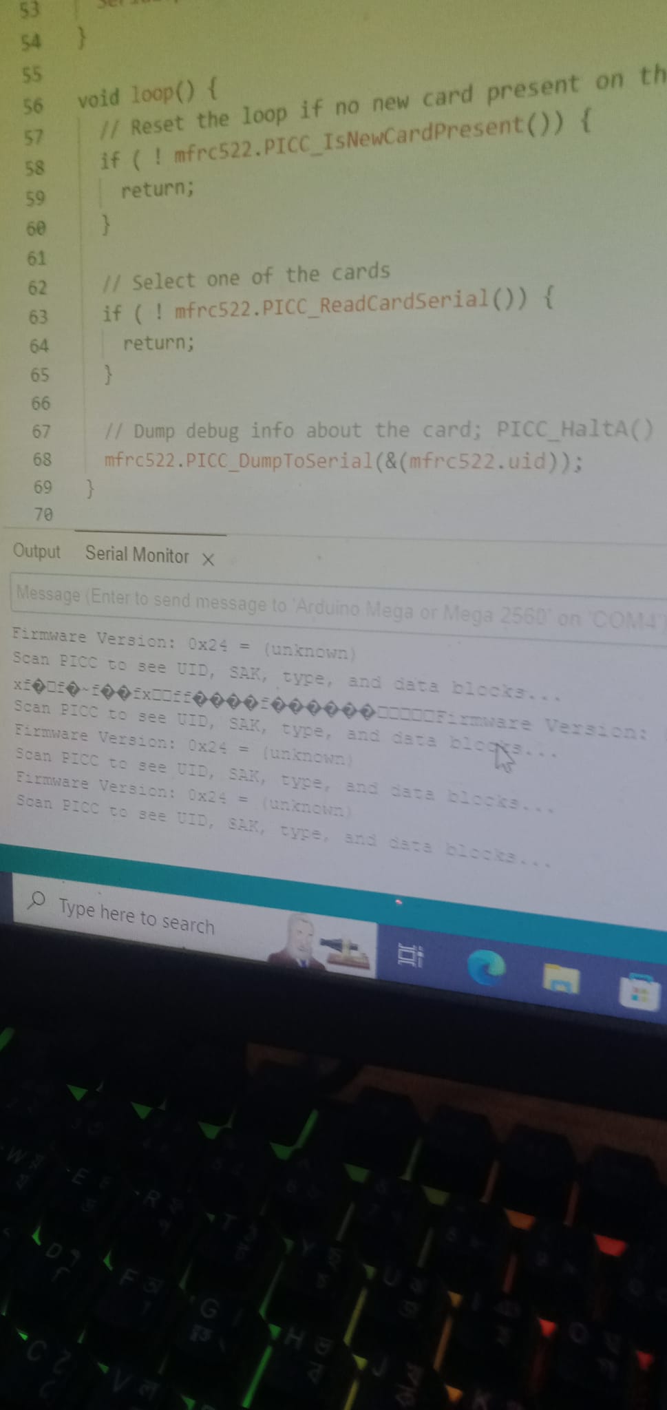
But when I uploaded the Dumpinfo example to see the tags uid the RC522 didn't show any RFID tags even though RC522 is properly powered, and I checked all the wire continuity.
Does anyone know why it's happening and how to fix it?
Please post a schematic showing how the components of your project are connected. A picture of a hand drawn circuit would be better than your photograph. For instance, where does the ribbon cable go to and where do the twisted pairs bottom/right go to ?
You are apparently trying to run SPI signals over a couple of feet. If you're using the default SPI clock speed for the Mega (4MHz, I believe), that wiring could be problematic.
You've hooked a 3.3V peripheral up to a 5V board. Even if you used 3.3V for the power, the signals are still going to be 5V and the RC522 IC is not 5V tolerant. Don't believe me? Internet says it's fine? Read the datasheet and decide for yourself.
Yeah I tested it before I cut the wires, for some reason, it is powered but it's not scanning the RFID tag or if it does it's not sending that info to Arduino mega.
I think your 1st point is the problem. Do you know how to fix it?
I don't think that your 2nd point is the case because if that were the issue the blog that I have used to know the use case and way to use the RC522 with Arduino Mega 2560 would use a short of voltage divider but almost all the connections that I have seen in the internet all of them directly connect those communication pins to the digital pins of arduino mega without any way to lower the voltage.
When I follow the datasheet, and use a 3.3V regulator, and a level shifter, and short wiring, it works. Your way, by your own admission, isn't working. Good luck with your project.
The ribbon is to label where the wire goes in the Arduino mega and the twisted pairs are the wires that connect the RC522 with the Arduino mega it's a little bit under 2 feet
Interestingly when I tried to connect the RC522 to a breadboard and then use it next to the Arduino Mega at a short distance it worked just fine
but my problem is I have to use it 1.5-2 feet away from the Arduino mega
From your picture, I can see you did not maintain the twisted pairs of wires in your CAT6 cable. There are 4 pairs of wires twisted together. In normal use, one wire of the pair is data and the other of the pair is ground return for that signal.
I just used the CAT6 cable cuz I have it lying around my house and it has different colors to identify and doesn't have extremely long jumper wires so I thought it would be a good idea to make some by cutting normal jumper wires and adding CAT6 cable between them. Btw The CAT6 has 8 wires in total but the RC522 used 7 so 1 wire is left with no use.
yes, when I use the rc522 with a breadboard and normal jumper wires it works.
But I also checked the connection long jumper wire I have made and all the connection is perfect with very little resistance
You don't think this is a problem because the internet gets it wrong. Well most of the internet is powered by people who do not know what they are doing. In contrast to this forum which consists (mainly) of people who do know what they are doing. The post by @IoT_hobbyist has the correct circuit.
This is basically that circuit as a proper schematic, although I prefer lower resistor values.
Basically if you want an RFID reader to work at those sorts of distances then you need a different reader than the one you have. One with a serial output like an RS232 one.
The alternative is to have an Arduino, or some other processor providing these high frequency signals close to the reader in a combined module, and then just send the signals back to your main control Arduino.
I used to work in the access control industry and have designed RFID reader modules, so I do know what I am talking about.
Great! Thanks for your info! I will use a different reader.
Do you know some RFID readers that offer to work at a distance of 2 feet and are easy to get?
There are lots, but are not always cheap.
What sort of RFID cards do you want to read?
The reader you got was for so called smart readers. These work at high frequencies of about 13 MHz. They can be used to store data on them, for various purposes, like the Oyster card used by London Transport and can be topped up.
There are other low frequency readers that work in the 125 KHz region, sometimes called HID readers but that is just a trade name. They also can be used for access control, but use tags that just contain a ID number.
This one has the electronics at the reader end and so makes a remote module like I said you could do. RFID Shield
It's for a personal project for my school's science fair where I'm building a prototype of a house that can be controlled via an IoT app and many other things, where if I show a verified ID card a door will open and a SMS will be sent to a number with the ID card owner's name and the time he/she entered the room.
Kinda like an attendance system but for a gate.
I just have to put the reader 2 feet away from Arduino to put the reader on a wall.
I'm thinking of using another reader that can be used with Arduino Mega from 2 feet away.
I'm also thinking I have to show the demo tomorrow so if I don't manage to find that kinda reader I'll send an SMS with a code to the number that I used in the smi800l that is connected to Arduino mega 2560 to open the door.