Anyway, hey everyone. I'm just starting out in the world of embedded electronics. (I've done plenty of soldering and wiring in my day, this IC and microcontroller stuff is a whole new beast)
My first project is using the 555 timer, and before I go and buy all the parts I'd like to know if this thing is even going to work.
The goal is to have it alternate between the two relays every second or so. I tried running it through CircuitLab, but that was confusing and they kept wanting me to upgrade.
Where exactly would the diodes go? I get what you mean about being able to drive the relays - I know the 555 is not very strong in terms of current. I'll add some transistors.
Other than that, though, does everything else look alright? I've followed several guides so I'm hoping the rest of the wiring checks out.
Papkee:
The goal is to have it alternate between the two relays every second or so.
I don't understand why you have two changeover relays being driven in the opposite sense. Can't you drive them in the same sense and just swap the NC/NO connections of one of then around? And, given that change, do you actually need two relays? A single relay with the appropriate number of poles would reduce the component count, complexity etc considerably. The circuit suggests that you expect the two relays to switch over simultaneously but if course it will never be absolutely simultaneous, and with two relays being driven independently you could easily end up with transient states where both or neither of them have switched. If that might be a problem, you should definitely rethink your design.
@PeterH
I was think the same thing, but being that we don't know what the circuit is going to be used for, I didn't bother to question it.
@Papkee
You do know there is a formula to compute the frequency, right.
1.44 / (R1 + R2) * C1 = Freq
With your values, your frequency is 1.97Hz, also R1 and R2 should be swapped and don't worry the frequency will stay the same.
Papkee:
It's supposed to be very close to the same. I know with the 555 a true 50% duty cycle is hard to get. Is there some easy approach I don't know about?
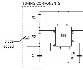
Yes include a diode across the resistor R2, so that the charge and discharge paths are independently controlled by R1 and R2.
I found this for you. 555Timers It should help you. Also I think the schematic in the link is wrong. It should be pin 7 going into the pot and pin 3 to the mosfet.
Can anyone confirm this?
Update:
This one is better. 555 Timer Look at example 4.1
It would have worked just fine with R1 = 5.1k and R2 = 150k. Pin 7 can absolutely take 1mA of current. I've done 555 circuits with 470 ohms as R1.
You would need the diodes across the relays. And you did figure out that you didn't really need two relays. However, as long as the relays are low enough current, you could drive two relays in that manner with a 555. Having them connected that way does not create a short circuit.
As for the diode: Charge time will be a little longer because it charges through R1 -and- D1, therefore with Vcc=5V you are dropping 0.7V, it is worse than it looks because it is charging from one-third of Vcc to two-thirds of Vcc, which means you are losing not 0.7V out of 5V, but 0.7V out of 3.33V. Which is about 20%. Please not that this does -not- translate directly into duty cycle. I built the circuit in LTSpice and got about 54.7% duty cycle.
Whereas if you use it as you originally designed it, I built it in LTSpice and got a 50.8% duty cycle. Do you really need it better than that?
If so, I'd suggest using a CMOS 555 like the TLC555, then use R1=1k and R2=2.2M and C1=0.33uF. You don't really want to use an electrolytic capacitor in a timing circuit as the tolerance is poor and they tend to have higher leakage currents, and ceramic caps at 4.7uF are -very- voltage sensitive. You can get a poly or mylar capacitor in 0.33uF, and that gives you about 1Hz, same as the circuit you designed.
The first circuit was perfectly correct. The duty cycle was as near to 50% as you could judge by eye, and it is indeed for an indicator on a car.
Having two relays was somewhat superfluous. If you needed two sets of changeover contacts, it could have been advantageous as the NE555 is limited to 200 mA output drive capability and a DPDT relay may require more drive current than a SPDT. While the NE555 probably can handle relay "kickback" within its output current rating (which in fact, such kickback always is) either in its totem pole or parasitic diodes, a diode across each relay is always appropriate. Adding resistors is however, nonsense - you would be reducing the available drive current to the relay and making things more difficult.
As the relay may require more than 200 mA, the transistor driver in the second circuit would be preferred. I forget what I used when I first constructed a NE555 timer box some 40 years ago.
I added a second relay driven by the power supply just so one light wouldn't be on all the time.
Based on your schematic, as soon as you supply power to the circuit, relay1 will turn on, which then supplies to relay2. So either way one light will be on all the time. Why not just use a SPST switch and get rid of relay1, but then you will have to manually control whether the lights are on or not.
Unless, the power supply to the lights it different than the power supply to the circuit, in which case,its ok to do that and the circuit is good.
Add: I had my relays backwards.
Edit: I didn't realize you took out the resistor going from pin 3 to the transistor, thank polymorph for spotting that. karma for polymorph.
You need a resistor from pin 3 to the base of T1. Something that allows 1/10th of the required relay coil current to flow into the base. Transistor Beta drops drastically when in saturation.
Although you do not have the top relay connected to a transistor or IC directly, it is connected to everything via the power supply. So I still highly recommend a diode across that relay coil, too.