Hm ok, yes that was the pin mentioned on SFE's page...
I see that the RTS# pin is also connected to reset but I can believe it's not it's purpose.
How will I do?
I need to finish my case according to the new connector because in two weeks I will not have anymore the facilities...
How would I have to modify this one SparkFun USB to Serial Breakout - FT232RL - BOB-12731 - SparkFun Electronics to make it work at 5V? Just clearing the solder jumper and connecting the VCCIO to the 5V of my Arduino? Will it work without additional components or would I have to copy this part of the Arduino schematic?
Perhaps it's simpler to take Sparkfun's 3,3V version and modify it (like before they made the 5V version), but since they changed their design I'm not sure what to do...
I have that sparkfun FTDI board and I modified it for 5vdc operation.
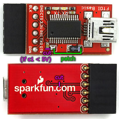
Looking at the linked schematic you will see a trace option for modifying the FTDI I/O voltage option. You cut the trace connection at the location labled SJ2 (solder jumper 2) with an sharp knife and then you solder a wire from from the tops of pin connector #4 of JP1 (VCC which is +5vdc) to pin connector #4 of JP2 (VCCIO which is the I/O voltage input to the FTDI chip). Finally you wire a .1mfd ceramic cap from pin #2 of JP2 DTR signal) to the reset pin on your AVR chip.
but it as been slightly updated so I can not copy what I see in the comments links.
If it has been updated from the unit you have then I don't know how to help you without a schematic of the exact one you have. This module already has the DTR signal on the connector, so you only have to have a .1mfd capacitor wired from that pin to your standalone processors reset pin.
Basically the I/O voltage change would work the same. Cut the trace that is suppling 3.3vdc to pin 4 of the FTDI chip and solder a jumper from that pin 4 to pin 20 of the FTDI chip.
Sorry if I express myself badly.
I don't have one at the moment. But
Look what they did : http://whosawhatsis.com/paraphernalia/ftdi_basic_5v.jpg
and what a commenter showed recently (comment on august 17th) http://www.flickr.com/photos/28914418@N02/3830391399/
So I don't really know what I do if I buy it. There is no more a jumper on the upside but some solder pads on the bottom. The pads doesn't appear on the (older) schematic...