Hello to everyone ! I am building a weather station, one of my main components for it is the wind vane.
I have explored this topic a lot, looking for different sensors, etc, but suddenly this crazy idea come into my head.
Has any of you tried fitting a compass sensor inside a wind vane? In this case the problem it's not more electronic i guess, its more mechanical,
I am planning to use a MPU 9250, so i can get tilt compensation.
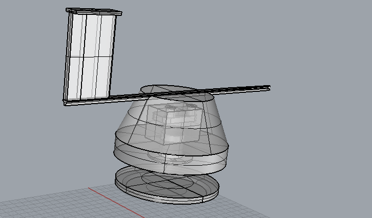
The idea is to fit the sensor inside the wind vane body, something like this:
It’s another way that I will explore, however this other idea, makes my job little easier so I don’t need to do calculations between anemometer north and magnetic north.
Is there any way to send wireless readings to the arduino? That would make the job much easier, I think that my only main limitation right now is the cable torsion
I was looking at the NRF24l01. Maybe fitting one of those and an arduino nano inside the wind vane central body can get me rid of the problem of the cables.
Now I am getting into the problem of the power inside the wind vane for the nano unit lol
Bear in mind that the wind changes slight direction second by second ( look at wind vane moving about ) so it may be pointless trying to get very accurate readings , certainly correcting for magnetic north is a bit over the top .
The usual method is 8 Reed switches and a magnet on the vane. Simple and reliable ( important when it’s out in all weather)
Worth experimenting before you build, need to think how accurately do you need to measure , rather than what’s possible .
I need to get +- 3 degrees of precision, I would use it for sailboat racing, where the angles are really important for performance.
But I still want to get this in a budget build.. so its very challenging.
I am thinking that would not be a bad idea doing a wireless sensor transmitting to a arduino unit below...
I could use a Seeduino Xiao that it's very small and a NRF24l01 + a lipo 3.7 batterys.
I'll wait until the slip ring arrives so i can check the resistance for the cables spinning anyway
Hello to everyone!
I am looking forward to create a wind vane where I will sit a tilt compensated compass inside so i can get good readings.
Which is the best way for achieving this?
I've seen some MPU9250, and some LSM303DLHC, and even some HMC5883L with adxl345
Hi paul, thanks for your reply:
My idea is fitting only the compass unit inside the body of the wind vane. To avoid cable torsion, I am using a low resistance Slip ring, Perhaps this model explains littlebit better:
By doing this i can get rid of using a standard windvane that uses resistances inside, cause anyway I need the compass for compensating windvane north vs magnetic north.
A windvane's axis is meant to point into the wind, not North, that doesn't make it's reading wrong.
I'm not trying to be difficult here, I am interested in windvanes. I also have one of those windvanes with resistances and reed switches inside, and I have imagined other ways that they could be designed. So I'd like to understand your design, but right now I don't get it.
If this was a portable windvane, I could see the benefit of using a tilt compensated compass inside. The user would not have to orient the windvane to North, or find a perfectly level surface to place it on for each use.
But for a permanently installed windvane, you would calibrate it for north and check that it was level during installation.
One design that would remove the need for reed switches and resistors would be to mount a bar magnet in the rotating part of the windvane and mount a magnetometer in the static part. The magnetometer could then be used to detect the orientation of the magnet. No slip ring would be needed.
I would not expect the wind vane to report anything but apparent wind direction relative to the boat. Any translation to true wind readings would be done elsewhere using data from the primary compass, at least on any racing setup i have used.