I am building a button box for sim racing. I purchased the plans from AMStudio but want to make some modifications.
I want to change one of the momentary push buttons to a latching toggle switch. I also would like to wire in an LED to indicate whether the toggle switch is on or off. The code part of it I have sorted out. Now I am just trying to figure out if I can wire in an LED in the current matrix setup.
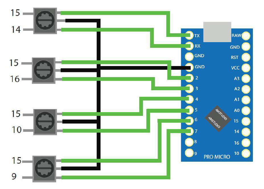
The pictures below show the wiring of the buttons and encoders. For clarification, I will exchange the top left push button for a latching toggle switch. I will also add diodes after each switch to avoid ghosting.
The toggle switch I have is a SPST switch. I know 1 solution would be to get a DPST switch and wire the LED to 5V and ground with a current limiting resistor in the circuit.
My question to you guys is, if I can wire in an LED with the current SPST switch I have.
Thanks for your suggestion. That is an option indeed, but I like the idea of the actual physical button being as close to what is used in a real race car.
Yes, sure. Please see a picture of a race dash below;
For example, let's assume the toggle switch with the red safety cover on it is the ignition switch. I have the same switch. I just want an LED above it that goes on when the switch is turned on. Does that clarify my question a bit more?
I see four Alarm lights at the top of the upper panel. I would expect all of those the be run from either the computer, or directly from a sensing mechanism.
For the lower panel I see four more LEDs. For the two on the right for fan and oil, I am assuming their switches turn on a fan and the oil pump respectively. In which case I would only want that LED to come on if the device is actually functioning. Otherwise, what is the point of the LED?
As for the other two switches on that panel that are unlabeled, I would want them to work in a similar manner.
To wit, I would say that @UKHeliBob question about doing it in software is closer to the mark than you imagine.
For the most part I'd expect most LEDs that are not directly integrated into a switch to be representative of a state of the machine and thus controlled elsewhere.
Perhaps I need to clarify; this button box will be connected to a computer and will act like a joystick/keyboard. I will then map the buttons to a function in game. For example, I will map the top left button in the matrix to the ignition. At the same time, I would like it to turn on an LED indicating ignition is on. Basically like the fan switch in the picture. Flip up the switch, LED turns on. I just don't know if the Arduino micro has enough pins left to control an LED or if I can wire in the LED in the current matrix or if I need to do anything else.
No, I got what you are saying. You can use a simple LED driver IC to control the LEDs with the Arduino and just a few pins and the keypad with a few more pins.
It will do exactly what you want without any real issue.
Check out projects that use Arduino and a MAX7219.
You can use it many ways and it will run up to 64 LEDs with only a few pins.
If you are going to use "latching" switches in a button matrix, and even if you do not but expect that more than two buttons may be pressed at any one time, you must use diodes on each switch contact.